Analysis apparatus having improved temperature control unit

a technology of temperature control unit and analysis apparatus, which is applied in the direction of heater elements, instruments, separation processes, etc., can solve the problems of difficult control of processes in a conventional air oven, virtually impossible to achieve rapid and accurate temperature control, and relatively complex electromechanical configurations to achieve even a minimal degree of temperature control. , to achieve the effect of convenient disengagemen

Active Publication Date: 2005-11-10
BECKMAN COULTER INC
View PDF5 Cites 33 Cited by
  • Summary
  • Abstract
  • Description
  • Claims
  • Application Information

AI Technical Summary

Benefits of technology

[0007] An apparatus for use in controlling the temperature of one or more substances passing through one or more microfluidics channels in an analysis device is set forth. The apparatus comprises a heating unit having first and second surfaces. The first surface of the heating unit is constructed so that it is at least partially exposed for cooling of the heating unit. The apparatus also comprises a thermally conductive medium that is disposed proximate the second surface of the heating unit. The one or more microfluidics channels are disposed in the thermally conductive medium. In one embodiment, the one or more microfluidics channels are in the form of a plurality of capillary columns, such as those used in instruments for capillary electrophoresis. Each capillary columns is substantially surrounded by the material forming the thermally conductive medium. In another embodiment, the thermally conductive medium, along with the corresponding plurality of capillary columns, can be easily disengaged from the heating unit in a non-destructive manner thereby allowing the heating unit to be reused.

Problems solved by technology

However, such processes are often difficult to control in a conventional air oven.
Rapid and accurate temperature control is virtually impossible to achieve.
Relatively complex electromechanical configurations are also required to achieve even a minimal degree of temperature control.
However, the present inventors have recognized several disadvantages inherent in the design of this apparatus that can make it unsuitable for CDCE applications (as well as other temperature dependent analytical processes) on a large commercial scale.
For example, it is difficult to efficiently and economically incorporate the apparatus into existing analyzer designs.
Generally speaking, the apparatus can also be difficult to manufacture and use due to its complex design.
In addition, the temperature of the apparatus is difficult to accurately reset to an initial target temperature.
This may make the apparatus difficult to use in processes requiring a rapidly varying temperature profile.

Method used


Image

  • Analysis apparatus having improved temperature control unit
  • Analysis apparatus having improved temperature control unit
  • Analysis apparatus having improved temperature control unit

Examples


Embodiment Construction

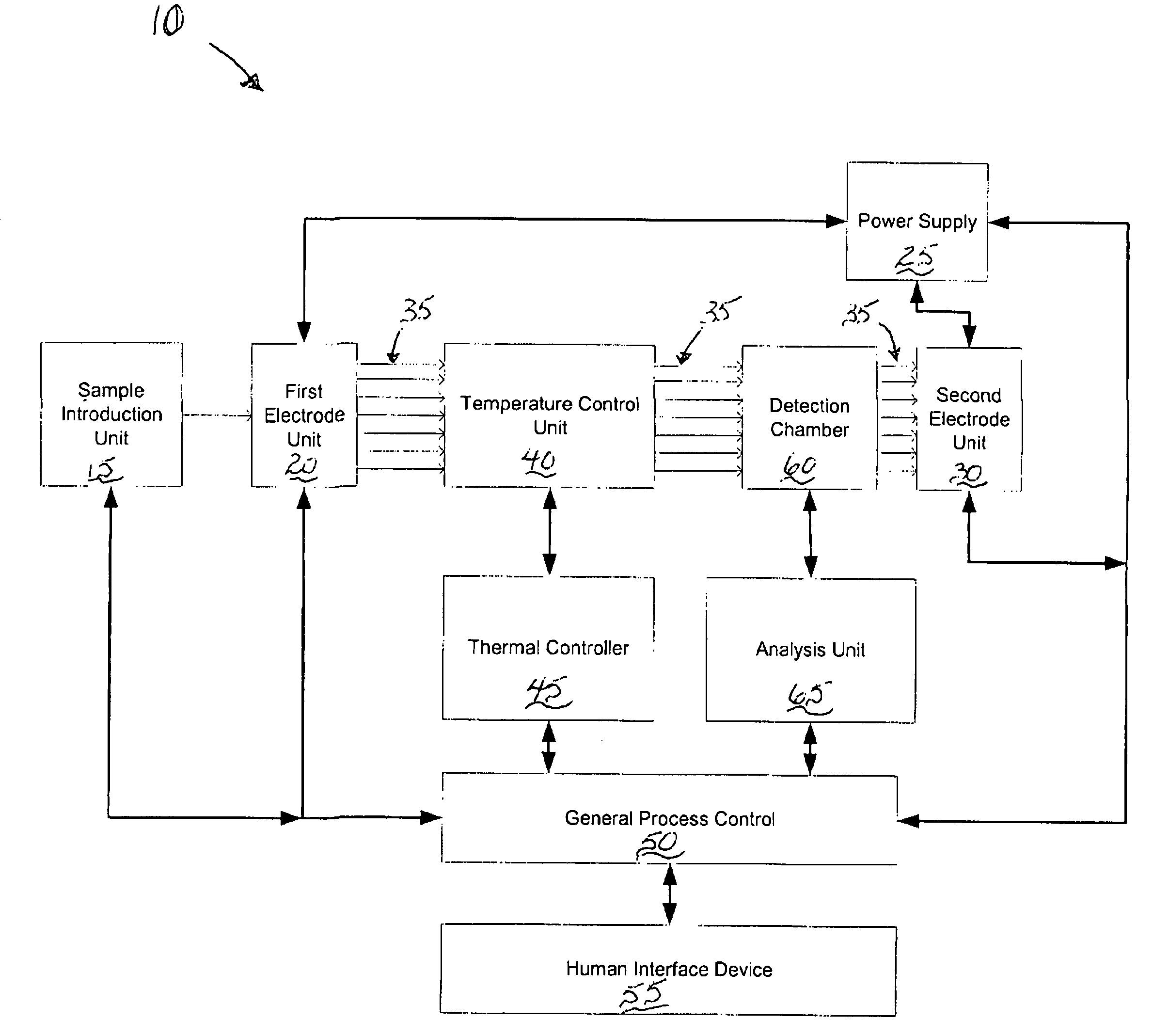
[0020] The apparatus of the present invention can be adapted for use in a wide range of biological and chemical analysis instruments that require static and / or varying temperature control of a substance passing through a microfluidic flow channel, such as a capillary column. For example, the apparatus can be adapted for use in instruments employed in flow cytometry, liquid chromatography, gas chromatography, capillary electrophoresis, etc. For purposes of the following discussion, various embodiments of the apparatus will be described in the context of a capillary electrophoresis system suitable for constant and / or varying temperature processes.

[0021]FIG. 1 illustrates one embodiment of a capillary electrophoresis system, shown generally at 10. As shown, the electrophoresis system 10 includes a sample introduction unit 15 that provides one or more substances that are to be analyzed. The samples are provided to the input of a first electrode unit 20. The first electrode unit 20 typi...


PUM

PropertyMeasurementUnit
thickaaaaaaaaaa
thickaaaaaaaaaa
temperatureaaaaaaaaaa

Abstract

An apparatus for use in controlling the temperature of one or more substances passing through one or more microfluidics channels in an analysis device is set forth. The apparatus comprises a heating unit having first and second surfaces. The first surface of the heating unit is constructed so that it is at least partially exposed for cooling of the heating unit. The apparatus also comprises a thermally conductive medium that is disposed proximate the second surface of the heating unit. The one or more microfluidics channels are disposed in the thermally conductive medium. In one embodiment, the one or more microfluidics channels are in the form of a plurality of capillary columns, such as those used in instruments for capillary electrophoresis. Each capillary columns is substantially surrounded by the material forming the thermally conductive medium. In another embodiment, the thermally conductive medium, along with the corresponding plurality of capillary columns, can be easily disengaged from the heating unit in a non-destructive manner thereby allowing the heating unit to be reused.

Description

FIELD OF THE INVENTION [0001] The present invention is generally directed to substance analysis apparatus. More particularly, the present invention is directed to a chemical / biological analysis apparatus having an improved temperature control unit for controlling the temperature of a substance passing through a microfluidic channel, such as a capillary column. BACKGROUND OF THE INVENTION [0002] Accurate and reproducible temperature control is required for a large number of applications in biological and chemical analysis. Such temperature control may require either a stable constant temperature over a definite time period or a temperature that varies in a predetermined manner during the overall analytical process. In general, techniques for molecular separation often benefit from temperature control. Biochemical and biophysical reactions occurring in connection with cellular assays and assays for blood chemistry and immunology also frequently involve steps that require controlled te...

Claims


Application Information

Patent Timeline
Patent Type & Authority Applications(United States)
IPC IPC(8): B01L7/00B01L9/00G01N27/447
CPCB01L7/52B01L9/527B01L2400/0406B01L2300/1805B01L2300/043
Inventor DEKA, CHIRANJITMILLER, ARTHUR W.DELIWALA, SUNIL S.KARGER, BARRY L.
Owner BECKMAN COULTER INC
Why Eureka
Try Eureka