Stackable Cable Hanger

a technology of hanging racks and cables, applied in the field of hanging racks, can solve the problems of increasing installation complexity and cost, crowded tunnels, and crowded tunnels of antenna towers and or tunnels

Inactive Publication Date: 2005-11-10
COMMSCOPE TECH LLC
View PDF17 Cites 33 Cited by
  • Summary
  • Abstract
  • Description
  • Claims
  • Application Information

AI Technical Summary

Problems solved by technology

Antenna towers and or tunnels may be crowded due to the multiplicity of cables required for signal-carrying.
Besides a significant materials expense, extending the cable hangers into stacked configurations requires initial installation of longer threaded rod than necessary and or exchange of mounting hardware that momentarily removes support for the existing cables, increasing installation complexity and costs.

Method used


Image

  • Stackable Cable Hanger
  • Stackable Cable Hanger
  • Stackable Cable Hanger

Examples


Embodiment Construction

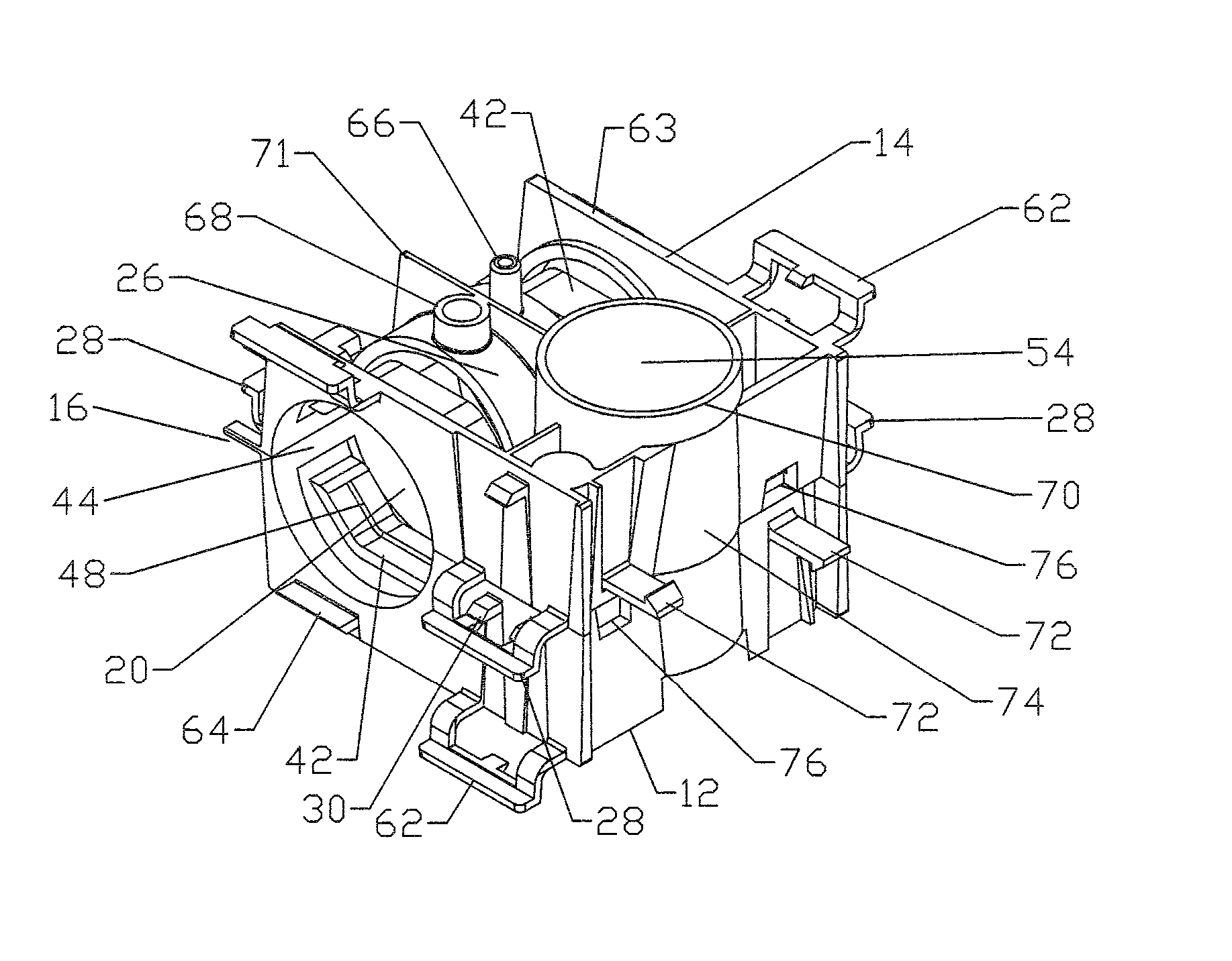
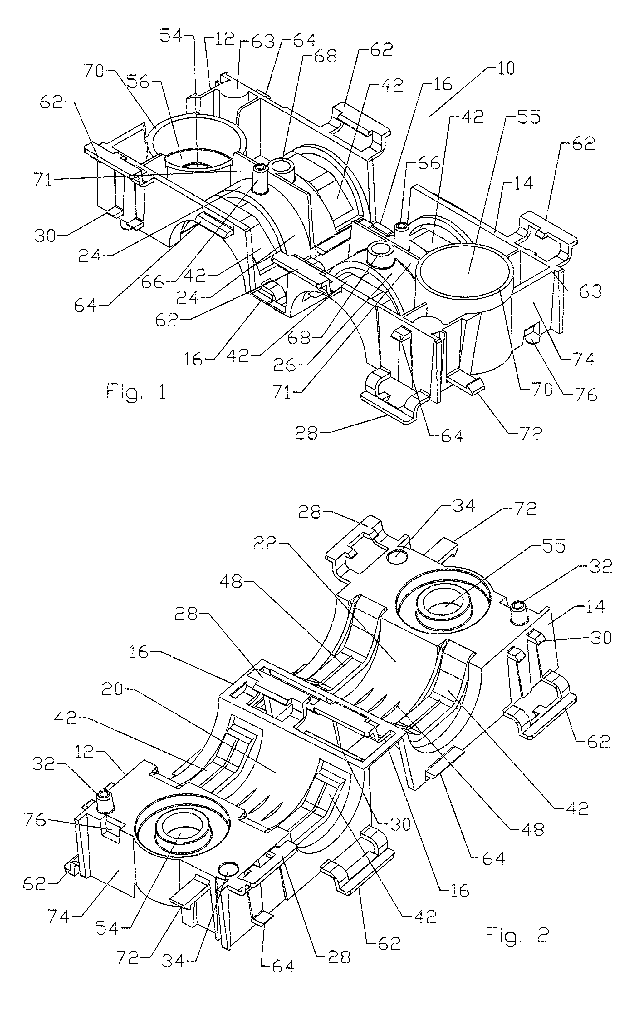
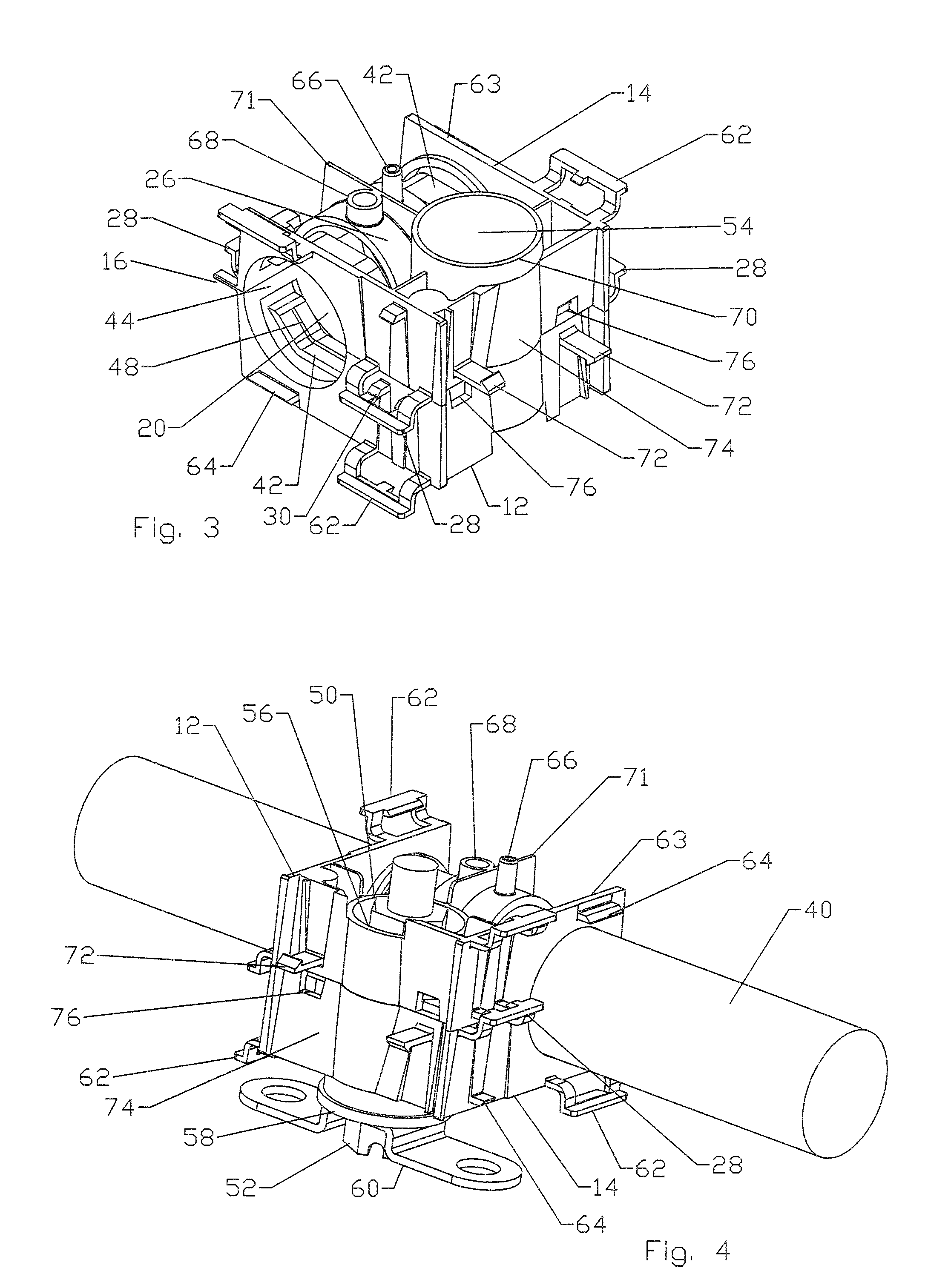
[0016] With reference to FIGS. 1 and 2, a cable hanger 10 of the invention includes a front shell half 12 and a rear shell half 14 that may be hingeably joined together by one or more spaced-apart assembly hinge(s) 16. The shell halves 12, 14 are folded or closed one onto the other to create an enclosing or encasing structure. When folded, respective front shell half inner surface 20 and rear shell half inner surface 22 of the shell halves 12, 14 have a confronting relationship and respective front shell half outer surface 24 and rear shell half outer surface 26 of the shell halves 12, 14 face away from each other in opposite directions. The assembly hinge(s) 16 may be provided for temporarily coupling the shell halves 12, 14 together for ease of manufacture and or distribution until folding for assembly and may be frangible. The relative thinness of the assembly hinge(s) 16 relative to the shell halves 12, 14 facilitates the folding of the shell halves 12, 14. Cable hanger 10 is se...


PUM


Abstract

A cable hanger having shell halves adapted to mate with each other, the shell halves each having an inner surface adapted to cooperate with the other to secure the cable within a cable space. The mating of the shell halves is releasably secured by a means for closure. A bolt hole through the shell halves allows easy mounting of the cable hanger. The shell halves each having, along a vertical mating surface, a means for interlocking adapted to interlock with the means for interlocking of a second cable hanger positioned against the cable hanger along the vertical mating surface. A connection side of the cable hanger may be adapted to have a means for latching to couple with a third cable hanger, positioned connection side to connection side with the cable hanger. The cable hanger allowing additional cables to be added without modifying the mounting of the base hanger.

Description

BACKGROUND OF INVENTION [0001] 1. Field of the Invention [0002] This invention relates generally to devices for supporting cables and, in particular, to hangers for securing cables to support structures. [0003] 2. Description of Related Art [0004] Cable hangers are commonly used to secure cables to structural members of, for example, antenna towers and or along tunnel walls. Generally, each cable is attached to a structural member by cable hangers mounted at periodically-spaced attachment points. [0005] Antenna towers and or tunnels may be crowded due to the multiplicity of cables required for signal-carrying. Over time, as systems are added, upgraded and or expanded, installation of additional cables may be required. To conserve space, it is desirable for each set of cable hangers to secure more than a single cable. Certain cable hangers have been constructed to secure multiple cables; other cable hangers have a stackable construction that permits multiple cable hangers to be inter...

Claims


Application Information

Patent Timeline
Patent Type & Authority Applications(United States)
IPC IPC(8): F16L3/10
CPCH02G3/263Y10T24/44Y10T24/44034H02G3/32
Inventor LOW, DAVIDHORVATH, RAYMONDCOX, ALBERTNOFZIGER, ERICKORCZAK, RICHARD
Owner COMMSCOPE TECH LLC
Why Eureka
Try Eureka