Automatic wheelchair brake device

a brake device and wheelchair technology, applied in wheelchairs/patient conveyances, wheelchairs, cycle equipment, etc., can solve the problems of user error, increased risk of falling and injury, user attempting to stabilize himself or herself while entering or leaving the wheelchair, etc., to achieve enhanced retrofitability, easy retrofitability, and preservation of normal folding operation

Inactive Publication Date: 2005-11-10
JERRY FORD CO LLC
View PDF29 Cites 19 Cited by
  • Summary
  • Abstract
  • Description
  • Claims
  • Application Information

AI Technical Summary

Benefits of technology

[0011] The present invention, through various embodiments, provides an automatic wheelchair brake device that addresses the deficiencies of the prior art attempts to provide a wheelchair with automatically applying brakes. In particular embodiments as will be described herein, the automatic wheelchair brake device is generally easily retrofittable to an existing wheelchair frame. The ease of retrofitability is enhanced by configuring the brake device to use existing fastening poin...

Problems solved by technology

Although the conventional manual brake mechanisms are sufficient for their intended purpose once engaged, the requirement that the user must remember to actuate the brakes leaves these devices susceptible to user error.
As a result, a user attempting to stabilize himself or herself while entering or leaving the wheelchair, is at an increased risk of falling and injury due to the freely moveable wheelchair moving out from beneath them.
The continuously biased state of the sensing lever creates uncomfortable pressure points that are continuously felt by the seated user.
Other attempts to invent automatic braking-devices for wheelchairs have resulted in undesirably complicated braking assem...

Method used


Image

  • Automatic wheelchair brake device
  • Automatic wheelchair brake device
  • Automatic wheelchair brake device

Examples


Embodiment Construction

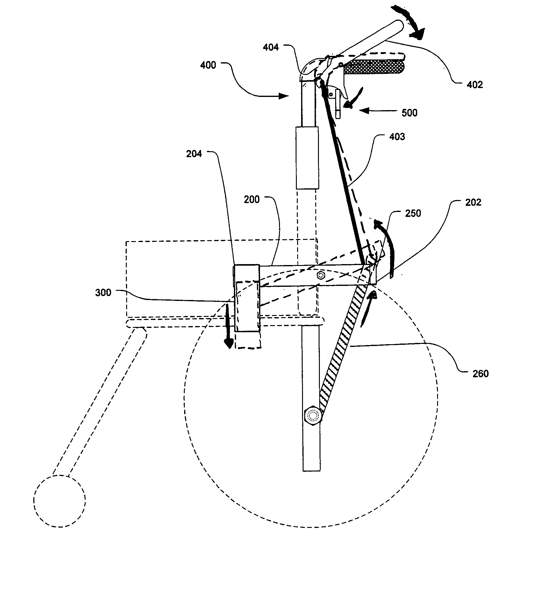
[0043]FIGS. 3-18 collectively illustrate a wheelchair with a weight-actuated brake mechanism, indicated by numeral 100, to control the free movement of the wheelchair. Referring generally to FIGS. 3-5C, and particularly to FIGS. 3 and 4, typically two wheelchair brake mechanisms 100a (in an exploded view) and 100b are attached to a wheelchair 102. Each wheelchair brake mechanism 100a and 100b controls the rotational movement of each of drive wheels 110a and 110b respectively. The following description of the wheelchair brake mechanisms 100a and 100b will be discussed singularly, but it should be noted that it applies equally to both mechanisms 100a and 100b.

[0044] The wheelchair brake mechanism 100a includes at least one support structure 200 comprising an elongate bar that is pivotally coupled to a portion of the foldable frame 108. Although an elongate bar is shown and discussed as one of the example embodiments, it should also be noted that the support structure 200 may also com...


PUM


Abstract

The present automatic wheelchair brake device invention includes a brake mechanism adapted to be installed on an existing collapsible wheelchair. The brake mechanism may be adapted to be operably installed on only one side of a frame of the collapsible wheelchair such that a side-to-side collapsibility of the frame of the collapsible wheelchair is significantly unimpeded by the brake mechanism. The brake mechanism may be movable between an engaged position that generally inhibits rolling movement of the wheelchair and a disengaged position permitting free rolling movement of the wheelchair in response to movement of structure on the one side of the frame of the collapsible wheel chair between a first position when the wheelchair is occupied and a second position when the wheelchair is unoccupied.

Description

PRIORITY [0001] This application claims the benefit of provisional patent application Ser. No. 60 / 602,125 filed on Aug. 17, 2004, and provisional patent application Ser. No. 60 / 567,907 filed on May 4, 2004, both of which are incorporated herein by reference in their entirety.FIELD OF THE INVENTION [0002] The invention generally relates to braking devices for wheelchairs. More particularly, the invention relates to an automatic wheelchair brake device weight-actuated brake mechanism for wheelchairs that is automatically actuated depending upon the position of the user with respect to the wheelchair. BACKGROUND OF THE INVENTION [0003] A conventional manual wheelchair is illustrated in FIGS. 1 and 2. Conventional manual wheelchairs 50 typically comprise a foldable frame 52, a seat 54 and a backrest 56, and a pair of manual brake mechanisms 58a and 58b. Two large drive wheels 60a and 60b are typically rotatably mounted to the foldable frame 52 to permit a user to operate and move the wh...

Claims


Application Information

Patent Timeline
IPC IPC(8): A61G5/08B62B5/04B62H1/00
CPCA61G5/1018A61G2005/0825A61G2005/1054A61G5/1037A61G5/101A61G5/1035A61G2005/127A61G5/0825A61G5/1054A61G5/127
Inventor FORD, JERRY
Owner JERRY FORD CO LLC
Why Eureka
Try Eureka