Method and apparatus for DC offset removal

a technology of offset removal and dc, applied in the field of electronic communication, can solve the problems of reducing the physical size of electronic devices, increasing the complexity and performance of devices, and imposing tremendous constraints on ongoing developmen

Active Publication Date: 2005-11-10
MAXLINEAR INC
View PDF28 Cites 33 Cited by
  • Summary
  • Abstract
  • Description
  • Claims
  • Application Information

AI Technical Summary

Problems solved by technology

The trend of increasing device complexity and performance while simultaneously reducing the physical size of electronic devices imposes tremendous constraints on ongoing development.
Although the screen size available in television receivers continues to grow, the advancement of technologies that enable flat screens and short depths greatly reduce the volume available for electronics.
The complexity and corresponding performance of digital circuits, such as processors, has increased tremendously.
However, the advancement of analog circuits, particularly analog circuits for use in Radio Frequency (RF) applications, has not experienced the tremendous advancement seen in digital circuits.
As such, device miniaturization and communication system performance enhancement can be limited by the performance of the analog portions of a device, including the RF portions of the device.

Method used


Image

  • Method and apparatus for DC offset removal
  • Method and apparatus for DC offset removal
  • Method and apparatus for DC offset removal

Examples


Embodiment Construction

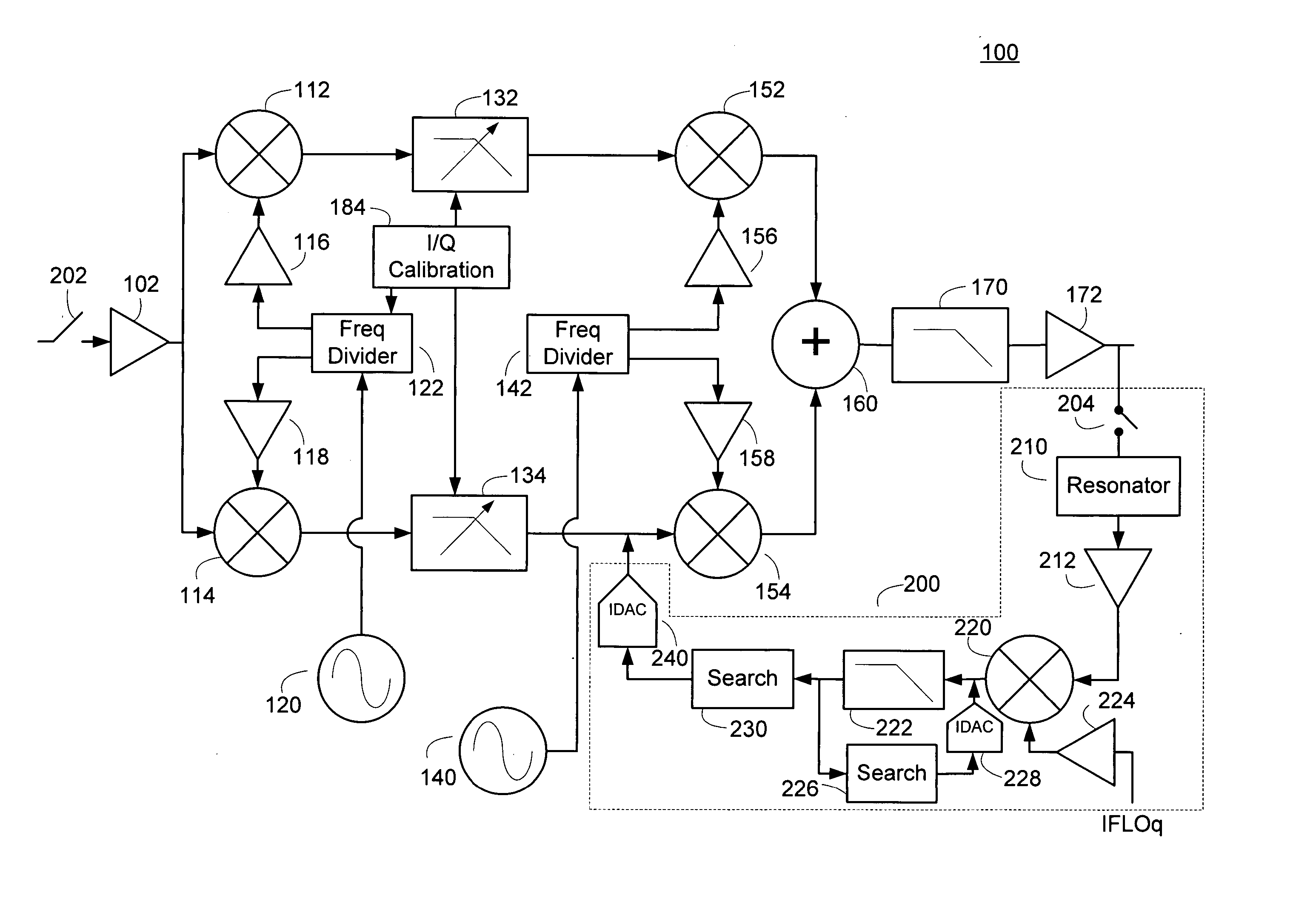
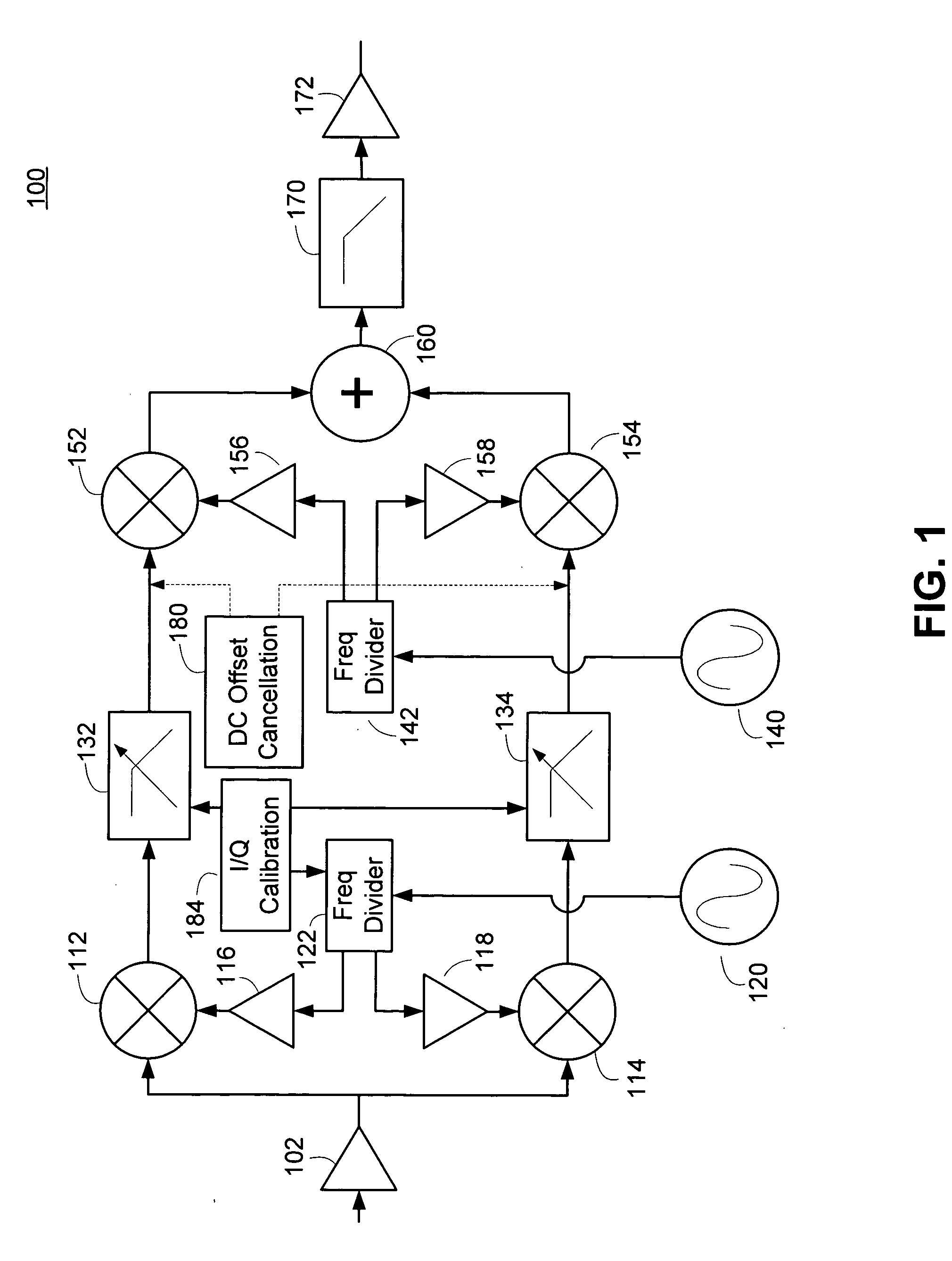
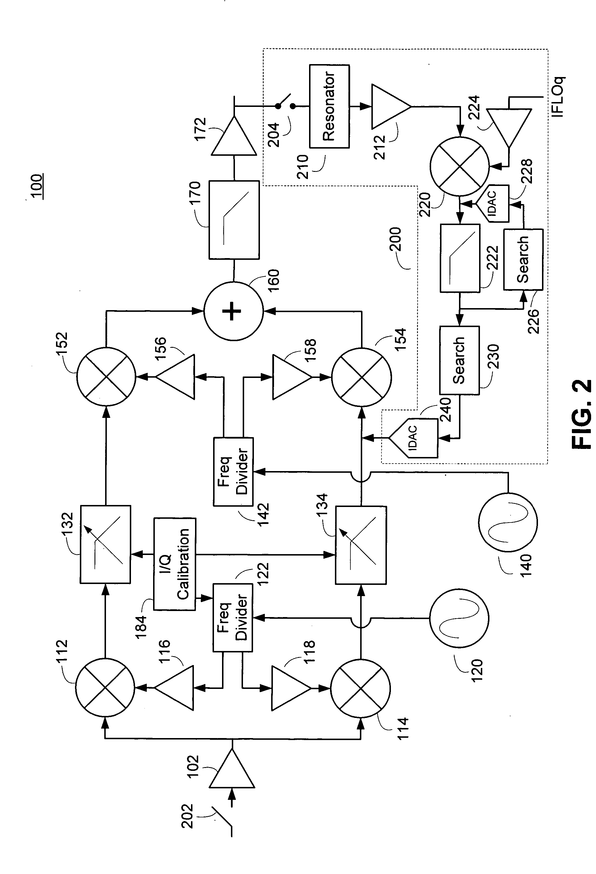
[0028] The disclosed dual conversion receiver uses a two stage frequency translation and continual DC offset removal, and can be completely implemented on an integrated circuit with no external adjustments. The disclosed dual conversion receiver can be used for high-performance radio standards such as television by inclusion of a DC offset removal circuit. The DC offset removal circuit can operate continually and can be made to be sufficiently sensitive to remove unwanted offsets introduced by Local Oscillator (LO) leakage or mixer and baseband circuitry mismatches. In one embodiment, a variable low-pass filter at baseband can be configured to accommodate multiple standards such as those found in television. Embodiments may also include a variable second local oscillator frequency configured to produce a variable intermediate frequency to accommodate multiple demodulator requirements.

[0029] A downconversion receiver system may require mechanisms for removing undesired DC offsets in...


PUM


Abstract

A DC offset removal method and apparatus for use with a receiver, such as a direct conversion receiver. The DC offset error can be upconverted to an intermediate frequency where it appears as a DC offset spurious signal. The DC offset spurious signal can be amplified and downconverted back to a DC signal. The DC signal can be used to determine an offset correction value that can be coupled to a signal path to substantially remove the DC offset error. An embodiment is disclosed that allows a single module to be used to remove the static and dynamic DC offset error components. Another embodiment includes separate portions for the removal of static and dynamic offset errors.

Description

CROSS-REFERENCES TO RELATED APPLICATIONS [0001] This application claims the benefit of U.S. Provisional Application No. 60 / 562,080, filed Apr. 13, 2004, entitled “DUAL CONVERSION RECEIVER ARCHITECTURE WITH PROGRAMMABLE INTERMEDIATE FREQUENCY AND EFFICIENT CHANNEL SELECTION SUITABLE FOR COMPLETE INTEGRATION ON A SINGLE INTEGRATED CIRCUIT” and U.S. Provisional Application No. 60 / 562,072, filed Apr. 13, 2004 and entitled “REMOVAL OF DC OFFSET IN DIRECT CONVERSION RECEIVER,” each of which is hereby incorporated herein by reference in its entirety.BACKGROUND OF THE DISCLOSURE [0002] The disclosure relates to electronic communications. More particularly, the disclosure relates to a dual conversion receiver for use in electronic communication systems. [0003] In a typical frequency division multiplex communication system, multiple transmissions can simultaneously occupy a predefined operating band. The signals within the operating band can operate according to a predetermined communication ...

Claims


Application Information

Patent Timeline
Patent Type & Authority Applications(United States)
IPC IPC(8): H03D3/00H03M1/06H04B1/10H04B1/16H04B1/18H04B1/26H04B1/30H04L25/06H04L27/38
CPCH03D3/009H04L27/3863H04B1/30H04B1/1036
Inventor LING, CURTIS
Owner MAXLINEAR INC
Why Eureka
Try Eureka