Driving apparatus and method for light emitting diode display

a technology of light-emitting diodes and driving apparatuses, which is applied in the direction of electroluminescent light sources, static indicating devices, instruments, etc., can solve the problems of oled brightness that cannot be maintained, the efficiency of the oled itself declines with time, and the brightness pattern of overtime brightness cannot be prevented

Active Publication Date: 2005-11-10
OPTRONIC SCI LLC
View PDF1 Cites 15 Cited by
  • Summary
  • Abstract
  • Description
  • Claims
  • Application Information

AI Technical Summary

Benefits of technology

[0017] An advantage of the present invention is the preservation of LED brightness in spite of routine decay of LED material.
[0018] A further advantage of the present invention is the prevention of overtime brightness patterns due to inter-pixel inconsistencies.

Problems solved by technology

Judging from the current technology, however, the brightness of the OLED cannot be maintained, even if the electric currents provided by the TFT are kept constant.
This is because the efficiency of the OLED itself declines with time, and it declines faster than the TFT.
Therefore, according to conventional techniques, even when electric currents are kept steady by the TFT, the brightness of the AMOLED display still decays.
However, even with constant electric current, as can be seen from formula (1) above, the display's brightness will decline with the efficiency (E), which decays with time.
This is a serious problem.
A second problem occurs when the display is stationary for some time.

Method used


Image

  • Driving apparatus and method for light emitting diode display
  • Driving apparatus and method for light emitting diode display
  • Driving apparatus and method for light emitting diode display

Examples


Embodiment Construction

[0027] Reference will now be made in detail to the exemplary embodiments of the present invention, examples of which are illustrated in the accompanying drawings.

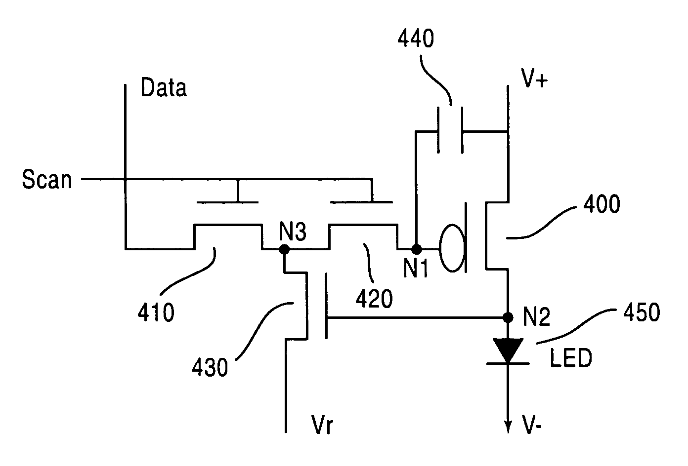
[0028] The present invention relates to an improved circuit and method for compensating for decreased brightness due to degradation in the materials for an LED.

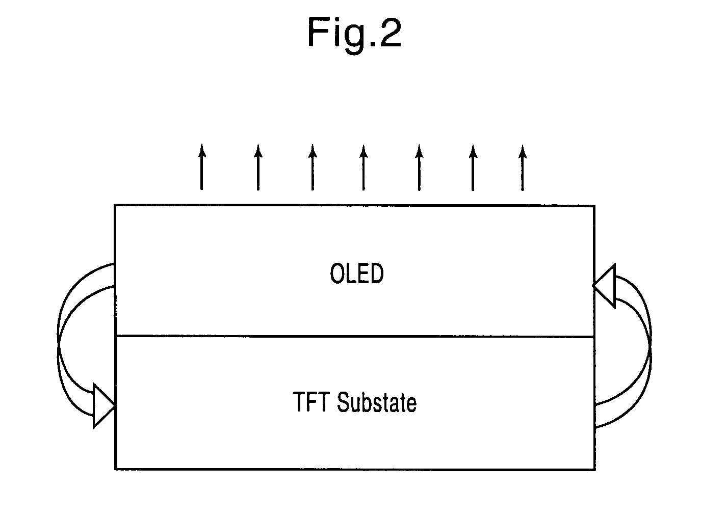
[0029] As shown in FIG. 2, the principle of this invention is to measure the level of LED materials decay, which will be sent to the TFT substrate. The TFT substrate, in return, will increase the electric current to areas of decay in order to maintain its original brightness. A more detailed description follows.

[0030] In FIG. 3, we see that because LED material decay (curve a) coincides with an increase in the LED's threshold voltage, there are two ways to measure LED material's decay. The first one is to ascertain the brightness of LED, and the second one is to determine the LED's threshold voltage. The present invention takes the second approach, that is, it det...


PUM


Abstract

The present invention provides a driving apparatus, method and system for a light emitting device, suitable for use in an active matrix organic light emitting diode (AMOLED) display, which has an adjustable reference voltage, so as to compensate for degradation in brightness due to LED materials decay.

Description

BACKGROUND OF THE INVENTION [0001] 1. Field of Invention [0002] The present invention relates to a technique for driving a light emitting device (LED), and suitable for an active matrix organic light-emitting diode (AMOLED). In particular, the present invention is directed to a technique for driving a light emitting device, and suitable for an active matrix organic light-emitting diode (AMOLED), such that the brightness of the display will not degrade as normal degradation of the materials occurs. [0003] 2. Description of Related Art [0004] The active matrix organic light emitting diode (AMOLED) display technology is a newly developed technology, and will be mainstream for display devices accompanying liquid crystal displays (LCDs) in the future. The major feature of the AMOLED display is the use of a thin film transistor (TFT) technique to drive the organic light emitting diode, and the driving integrated circuit (IC) is installed on the panel directly, so as to be small in volume ...

Claims


Application Information

Patent Timeline
Patent Type & Authority Applications(United States)
IPC IPC(8): G09G3/20H01L51/50G09G3/30G09G3/32H05B33/14H05B44/00
CPCG09G3/3233G09G2300/043G09G2320/043G09G2300/0842G09G2300/0819
Inventor LI, CHUN-HUAI
Owner OPTRONIC SCI LLC
Why Eureka
Try Eureka