Beam profile complex reflectance system and method for thin film and critical dimension measurements

a beam profile and complex reflectance technology, applied in the field of refractive ellipsometry, can solve the problems of not having the same capabilities, conventional bpe measurements suffering from phase fluctuations, and conventional bpr and bpe systems tending to be complex

Inactive Publication Date: 2005-11-10
ROSENCWAIG ALLAN
View PDF25 Cites 23 Cited by
  • Summary
  • Abstract
  • Description
  • Claims
  • Application Information

AI Technical Summary

Problems solved by technology

Furthermore, the ever-decreasing geometries translate into ever-decreasing measurement areas, and thus the requirements for ever-smaller measurement spots.
Conventional laser-based BPR and BPE technologies have the advantages of better signal/noise ratios and smaller spot sizes, but at present are only single wavelength devices, and thus do not have the same capabilities as the spectral technologies.
In addition, conventional BPE measurements suffer from phase fluctuations arising from the environmentally sensitive birefringence of the high-NA focusing objective.
Moreover, conventional BPR and BPE systems tend to be comp

Method used


Image

  • Beam profile complex reflectance system and method for thin film and critical dimension measurements
  • Beam profile complex reflectance system and method for thin film and critical dimension measurements
  • Beam profile complex reflectance system and method for thin film and critical dimension measurements

Examples


Embodiment Construction

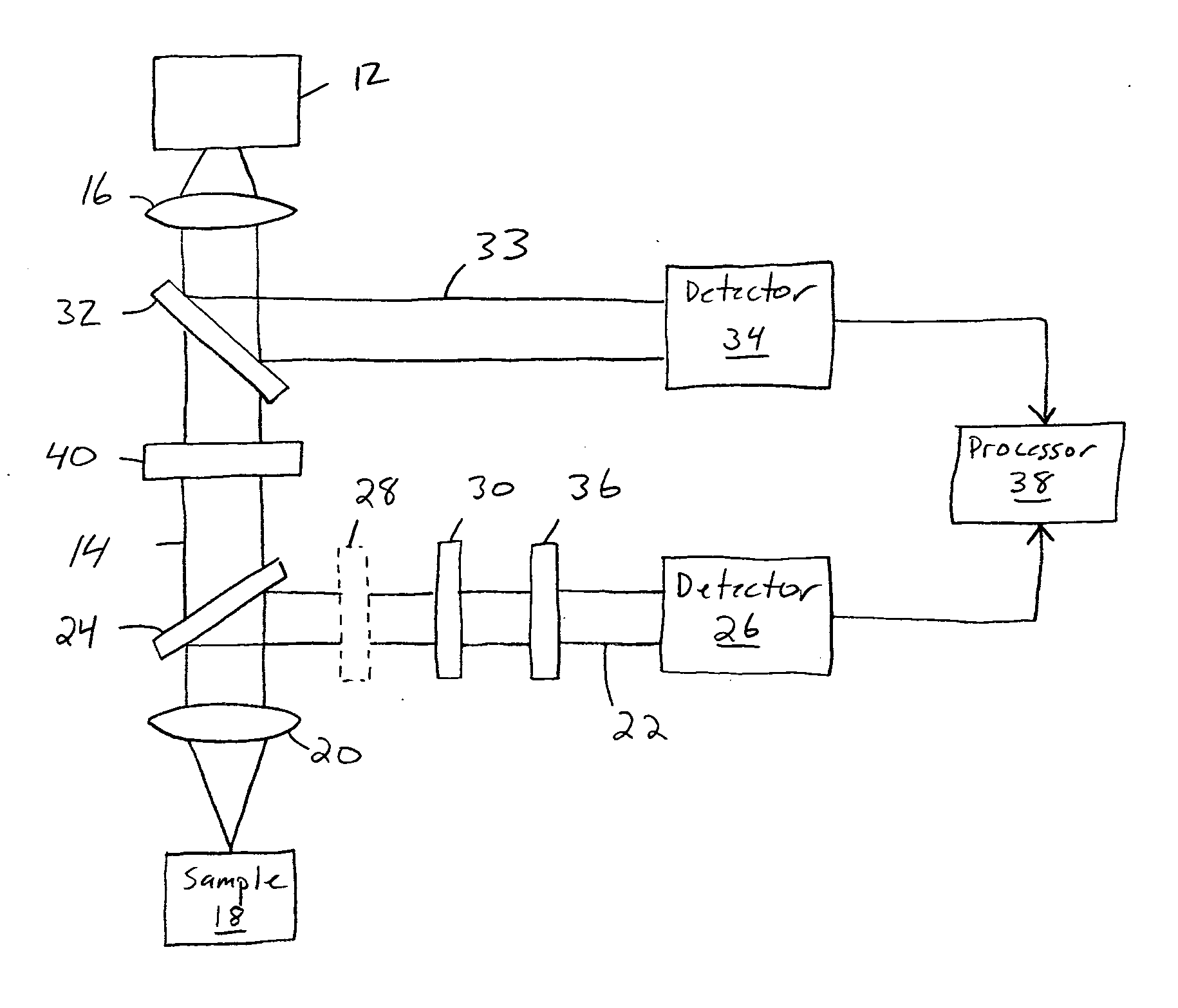
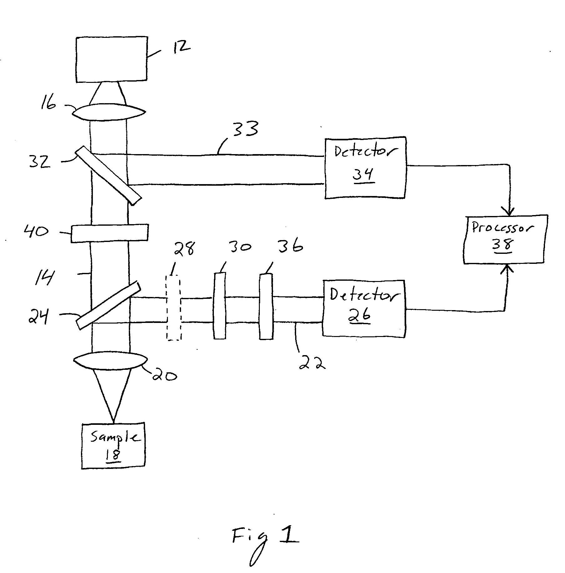
[0012] The present invention is a new and improved method and apparatus for measuring the thickness and optical constants of thin films deposited on substrates and of critical dimensions of circuit structures. More specifically, the present invention measures the spectroscopic complex reflectance from a sample surface, where both the magnitude and phase of reflected light from the sample is obtained simultaneously over a wide range of angles of incidence and over all azimuthal angles, and at different wavelengths, by combining beam profile reflectometry (BPR) and beam profile ellipsometry (BPE) measurements into a single measurement device and method using a single 2-dimensional detector. Thus, the combination of BPR and BPE using multiple wavelengths can be referred to as a spectral BP2 technology, to emphasize that it is a two-dimensional beam profile technology.

[0013] The optical probe beam is directed normal to the sample surface and is tightly focused by means of a high numeri...


PUM


Abstract

Device and method for measuring complex reflectance using a light source for generating a light beam with known polarization state, a lens for focusing the beam onto a sample surface such that various rays within the focused beam create a spread of angles of incidence θ, a waveplate for retarding one polarization state of the beam, a polarizer for generating interference between beam polarization states, and a detector with a two dimensional array of detector elements for generating intensity signals in response to the beam, wherein each detector element corresponds to a unique angle of incidence θ and azimuthal angle φ of the reflected beam. A processor calculates magnitude and phase values for the reflected beam by using the intensity signals corresponding to at least one incident angle θ and a plurality of azimuthal angles φ within the at least one incident angle θ sufficient to enable a meaningful Fourier analysis thereof.

Description

[0001] This application claims the benefit of U.S. Provisional Application No. 60 / 563,725, filed Apr. 19, 2004; and U.S. Provisional Application No. 60 / 568,215, filed May 3, 2004; and U.S. Provisional Application No. 60 / 610,896, filed Sep. 17, 2004; and U.S. Provisional Application No. 60 / 613,040, filed Sep. 25, 2004; and U.S. Provisional Application No. 60 / 624,865, filed Nov. 1, 2004; U.S. Provisional Application No. 60 / 640,182, filed Dec. 27, 2004; and U.S. Provisional Application No. 60 / 650,937, filed Feb. 7, 2005.FIELD OF THE INVENTION [0002] The present invention relates to reflectometry and ellipsometry, and more particularly to a method and system that combines reflectometry and ellipsometry for an improved technique in measuring thin film thickness, refractive indices, extinction coefficients and critical dimensions. BACKGROUND OF THE INVENTION [0003] Optical reflectometry and ellipsometry are commonly used to measure the thickness (t) and optical constants, refractive index...

Claims


Application Information

Patent Timeline
IPC IPC(8): G01B9/02G01B11/06G01N21/21
CPCG01B11/0625G01N2021/213G01N21/211G01B11/0675
Inventor ROSENCWAIG, ALLAN
Owner ROSENCWAIG ALLAN
Why Eureka
Try Eureka