Sconce-type lighting fixture

a lighting fixture and sconce technology, applied in the field of lighting fixtures, can solve the problems of high abuse of lighting environment, physical and/or environmental damage to lighting fixtures, and aesthetic design fixtures that do not provide the environmental durability necessary for public areas, and achieve the effect of water resistance and serviceability

Inactive Publication Date: 2005-11-10
KENALL MFG
View PDF23 Cites 4 Cited by
  • Summary
  • Abstract
  • Description
  • Claims
  • Application Information

AI Technical Summary

Benefits of technology

[0009] Another object of the invention is to provide aesthetically pleasing sconce-type lighting fixtures resistant to breakage such as that caused by vandalism or accidental impact from a foreign object and resistant to damage caused by their environment.
[0011] Still another object of the invention is to provide sconce-type lighting fixtures that provide both water resistance and serviceability.
[0012] Yet another object of the invention is to provide a scalable and modular design for sconce-type lighting fixtures.
[0014] A further object of the invention is to provide a sconce-type lighting fixture that may be easily assembled and installed.
[0019] The invention provides a lighting design methodology that combines aesthetics, ease of manufacturing, modularity, scalability, water resistance and channeling, safety, illuminating potentially hazardous areas, resistance to breakage and corrosion, resistance to litter, serviceability, adaptability, and other considerations. These practical considerations provide an improved sconce-type lighting fixture, and associated methods.

Problems solved by technology

In either case, a high abuse lighting environment may exist in a commercial facility, where lighting fixtures are subjected to a higher possibility of events and / or conditions that could cause physical and / or environmental damage to the lighting fixture.
However, such aesthetically designed fixtures do not provide an acceptable environmental durability necessary for public areas.
In addition, conventional sconce-type lighting fixtures are not designed to provide scalability, modularity, and easy assembly and installation.

Method used


Image

  • Sconce-type lighting fixture
  • Sconce-type lighting fixture
  • Sconce-type lighting fixture

Examples


Embodiment Construction

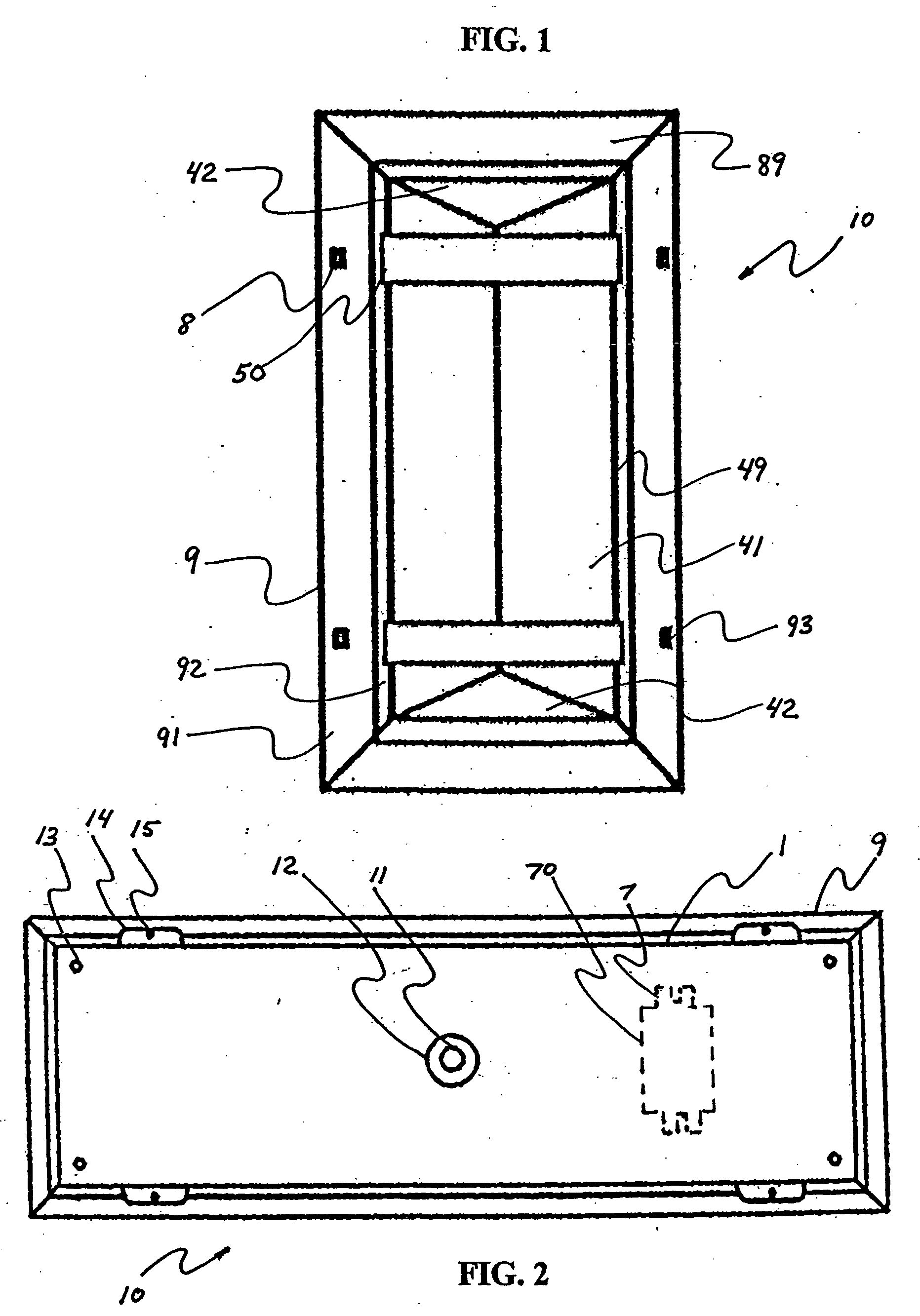
[0034]FIG. 1 is a front view of a sconce-type lighting fixture 10 according to an exemplary embodiment of the present invention. A lens 4 extends outwardly from a lens frame 9. Crossbars 5 are welded to lens frame 9 and protectively cover a portion of the outside surface of lens 4. Lens frame 9 has beveled portions 91, 92 that provide two uniformly angled surfaces facing out to the front of lighting fixture 10. Four mounting holes 93 are provided in lens frame 9 for accepting fasteners 8 that secure lens frame 9 to a rear portion of lighting fixture 10. The lens 4 shown in FIG. 1 is a “roof” type diffuser externally having two symmetric and adjoining side walls 41, and two symmetrically slanted end walls 42. As described further below, the profile of crossbars 5‘follows’ the shape of lens 4 to minimize any gap therebetween. This allows crossbars 5 to provide optimal protection while also providing an aesthetically pleasing appearance. Similarly, other shapes may be utilized for lens...


PUM


Abstract

A sconce-type lighting fixture includes a frame with an inside surface having an inwardly-facing groove with uniform cross-section, and a light-transmissive cover having peripheral tabs extending into the groove, thereby snugly holding the cover in the frame. A method of providing a sconce-type lighting fixture includes providing a convex diffusing lens having a plurality of tabs on its outer periphery, and providing a sconce having a frame with an inner perimeter channel that provides no special accommodation for receiving the tabs, where the convex diffusing lens is adapted for snap-fit of the tabs into the inner perimeter channel. A system includes a lens, and a lens frame having an inner perimeter lens channel for receiving the lens without accomodation.

Description

RELATED APPLICATIONS [0001] The invention is related to U.S. application Ser. No. ___,___, entitled “Lighting Fixture With Water Shunt,” incorporated herein by reference in its entirety.BACKGROUND [0002] 1. Field of the Invention [0003] The invention relates generally to lighting fixtures and, more particularly, to a sconce-type lighting fixture having improved durability and adapted for scalable and modular construction thereof. [0004] 2. Background of the Invention [0005] The architectural community uses indoor and outdoor lighting products to enhance the image of their facilities, both during the daytime and at night. Of course, tastes may differ, and lighting fixtures may also be selected with little regard for appearance. In either case, a high abuse lighting environment may exist in a commercial facility, where lighting fixtures are subjected to a higher possibility of events and / or conditions that could cause physical and / or environmental damage to the lighting fixture. [0006...

Claims


Application Information

Patent Timeline
Patent Type & Authority Applications(United States)
IPC IPC(8): F21V3/02F21V15/01F21V17/16
CPCF21V3/02F21Y2103/00F21V17/164
Inventor MCCARTHY, CHARLES A. III
Owner KENALL MFG
Why Eureka
Try Eureka