
Packet shaping device, router, band control device and control method

Inactive Publication Date: 2005-11-10
FUJITSU LTD
View PDF1 Cites 30 Cited by
  • Summary
  • Abstract
  • Description
  • Claims
  • Application Information

AI Technical Summary

Benefits of technology

[0018] Based on the above, a first object of the present invention is to provide a packet shaping device and method in which plural flows handled by network devices such as routers can be efficiently shaped (burst growth suppressed) without knowledge about the properties of each flow.
[0019] A second object of the present invention is to provide a router that can suppress burst growth and can prevent packet discarding without need for the recording of the information of each flow and, moreover, that can be used to ensure the QoS of each flow in a large-scale network.
[0030] Based on the packet shaping method and packet shaping device of the present invention, a large number of flows handled by network devices such as routers can be efficiently shaped (burst growth can be suppressed) without knowledge about the properties of each flow.
[0031] Based on the router of the present invention, the burst growth produced in a router can be suppressed and, as a result, the packet discarding can be prevented without the need for the recording of the information of each flow in the routers, and the QoS of each flow can be ensured in a large-scale network.

Problems solved by technology

The increased burst length produces undesirable outcomes that are increase in the buffer capacity of the next stage processor, increase delay time, and increase packet loss rate.
However, the configuration for achieving this necessitates knowledge of the property about the flow such as maximum burst length of the flow and the like and, apart from this, a leaky bucket shaping device is unsuitable for use in a large-scale network because a separate device is required for each single flow.
However, this technique of the background art is a technique for statistically suppressing burst length and is not a technique for the deterministic or logical suppression of the burst growth generated in a network.
An increase in the delay time of the packet at this time, that is to say, an increase in the time required to send the packet from the send host to the receive host, and packet loss have a bad influence on the quality of the sound and image carried by the packet.
The cause of increased delay time and packet loss is the increased burst length caused by burst growth in the network and, as a result, an increase in buffer capacity, an increase in delay time and an increase in buffer packet loss rate occur in the downstream flow routers in which the growth accumulates.
But in Intserv the information of each of the flows must be recorded in each router and, accordingly, with networks of increased size in which there is an increased number of flows, the system is very complex, very expensive, and unsuitable for actual application.
Although, by virtue of the fact that the routers need only record the operation of quality classes, the actualization thereof is simple, because the operation is implemented in batches, quality assurance of individual flows is impossible and the demands of a user cannot be met.
Although, as described above, a demand exists for a packet shaping device and method able to perform the efficient shaping (suppression of burst growth) of a large number of flows handled by routers without knowledge about the properties of each flow, no such packet shaping device and shaping method are currently available.
In addition, although a demand exists for the economical guarantee of the QoS of each flow in a large-scale network, no such effective technique is currently available.
One of the reasons for the generation of the QoS problem is the packet loss produced by buffer overflow that occurs in a router when a flow passes through a router.
When the buffer capacity of a router is smaller than the burst length of the flow that is input, that is to say, smaller than the length of the longest packet string that must be simultaneously stored in the buffer of the router, packet discarding and packet loss occur.
By virtue of the fact that prediction of growth is difficult, existing IP networks are designed on the premise that packet discarding occurs in the routers.

Method used


Image

  • Packet shaping device, router, band control device and control method
  • Packet shaping device, router, band control device and control method
  • Packet shaping device, router, band control device and control method

Examples


first modified example

[0090] (e) First Modified Example

[0091] As shown in (A) of FIG. 7, according to the embodiment described above, the packet batch-shaping device includes one input line / one output line and performs shaping one flow. But as shown in (B) of FIG. 7, a configuration in which the packet shaping of a plurality of flows is simultaneously implemented is possible. In configuration of (B) of FIG. 7, a packet batch-shaping device 1 comprise a plurality of sets of input line and output line, a memory 12 and an input / output monitoring timers 13 and 16 for each set, and a program for relating the said shaping flow. In this modification, there are two operational modes outlined below.

[0092] In the first operational mode, when a packet to which a pass time PT has been assigned arrives at each of the input lines #lin to #Nin, the packet batch-shaping device 1, in accordance with the shaping process ofFIG. 3, shapes each input packet and outputs to corresponding one of the output lines #lout to #N ou...

second modified example

[0094] (f) Second Modified Example

[0095] As shown in (A) of FIG. 8, according to the embodiment described above the suppression of burst length generated in one network device 2 is performed. But as shown in (B) of FIG. 8, it is possible to suppress the burst length generated in a plurality of sequentially connected network devices 2a to 2c.

first embodiment

[0096] described above, the burst growth in one flow can be effectively suppressed. In addition, burst growth of a plurality of flows is simultaneously suppressed as a batch and knowledge of the properties of each flow is unnecessary for suppressing the burst growth.

[0097] (C) Burst Growth Suppressing Router

[0098] (a) Router Configuration

[0099]FIG. 9 is a block diagram of a router for suppressing the burst length. The router selects a prescribed output link on the basis of the destination address of the IP header on the packets that constitutes the input flow and sends these to a gateway that corresponds to this output link. The gateway, on the basis of the header contents, separates the packets into QoS packets for which communication quality guarantee (QoS) is required and non QoS packets (best effort packets) for which communication quality guarantee is not required, and sends the packets to output links in a sequence that guarantees the communication quality of the abovementi...


PUM


Abstract

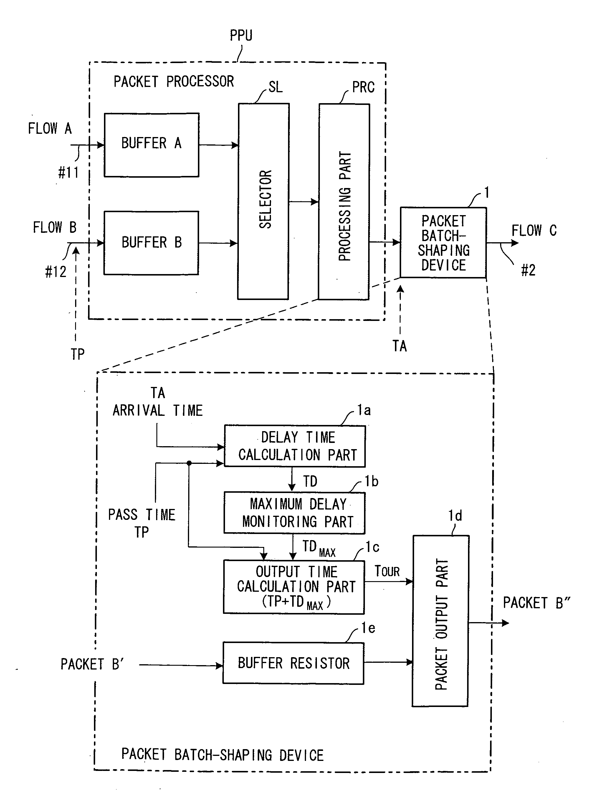
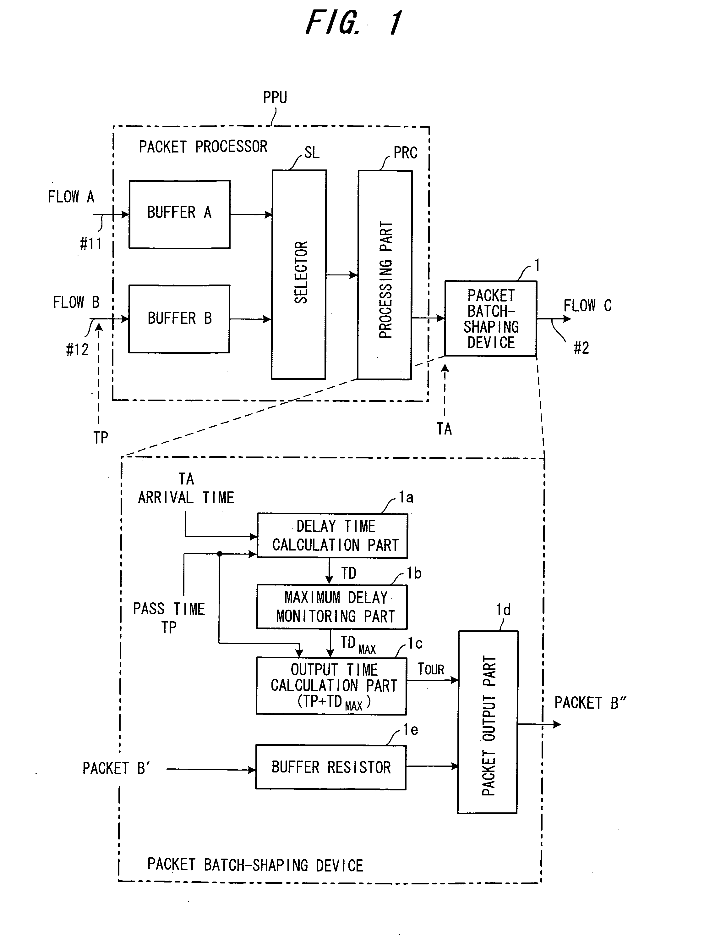
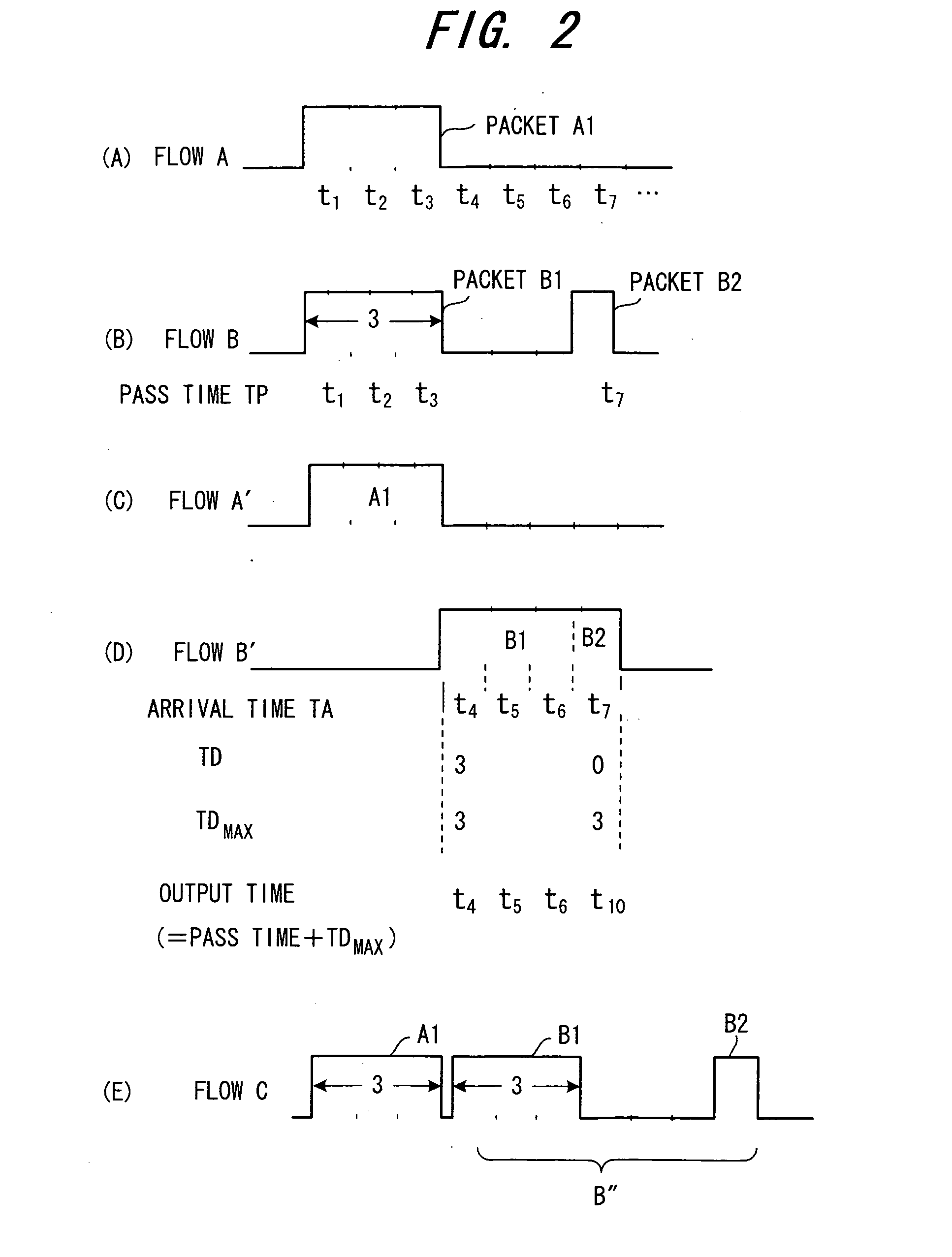
A packet shaping device for the purpose of shaping a packet in which burst has grown in a router to an original packet without the burst growth is disclosed. The packet shaping device monitors an arrival time TA of each packet on which a pass time TP is recorded when the packet passes a prescribed pass point and calculates a delay time TD which is a time difference between the pass time TP and the arrival time TA. Then, the packet shaping device obtains a maximum delay time TDmax among the delay times, and delays and sends all the arrived packets in such that the delay time of all the arrived packets is equivalent to the maximum delay time.

Description

BACKGROUND OF THE INVENTION [0001] The present invention relates to a packet shaping device, router, band control device and control method, and more particularly to a packet shaping method and device for performing shaping to the original burst length when burst of a flow consisted of packet strings grows in a communication device (network device), a router for suppressing burst growth, and a packet receiving control method and band control device for the configuring of a packet non-loss network. [0002] When packet strings pass through a packet processor such as a router a phenomenon occurs in which burst of an input flow grows. The burst specifies the maximum packet capacity necessary for storing simultaneously in the buffers. FIG. 27 is a block diagram of a packet processor for explaining burst growth, and FIG. 28 is an explanatory diagram of burst growth. Flows A, B are input into the packet processor through two input lines #11, #12 respectively, and are stored successively in ...

Claims


Application Information

Patent Timeline
IPC IPC(8): H04L47/22
CPCH04L47/10H04L47/11H04L47/21H04L47/283H04L47/2441H04L47/245H04L47/22
Inventor TODA, IWAOYAMADA, AKIKO
Owner FUJITSU LTD
Learn More