
Cam-driven pump mechanism for a battery-powered grease gun

a grease gun and cam-driven technology, applied in the direction of pump components, piston pumps, positive displacement liquid engines, etc., can solve the problems of periodic need for replacement of sliding blocks, erratically operating pump mechanisms, and unreliable pump mechanisms, and achieve the effect of prolonging the life of grease guns

Inactive Publication Date: 2005-11-10
TECHWAY INDAL
View PDF3 Cites 11 Cited by
  • Summary
  • Abstract
  • Description
  • Claims
  • Application Information

AI Technical Summary

Benefits of technology

[0010] The main objective of the present invention is to provide a cam-driven pump mechanism for a battery-powered grease gun, and the cam-driven pump mechanism keeps any part of the pump mechanism from wearing excessively to extend the life of the grease gun.
[0014] Consequently, use of the cylindrical cam prevents localized friction on the sliding block and keeps the parts of the pump mechanism from wearing excessively.

Problems solved by technology

This uneven wear eventually causes the pump mechanism to operate erratically and be unreliable.
Furthermore, the uneven wear makes replacement of the sliding block (68) periodically necessary.

Method used


Image

  • Cam-driven pump mechanism for a battery-powered grease gun
  • Cam-driven pump mechanism for a battery-powered grease gun
  • Cam-driven pump mechanism for a battery-powered grease gun

Examples


Embodiment Construction

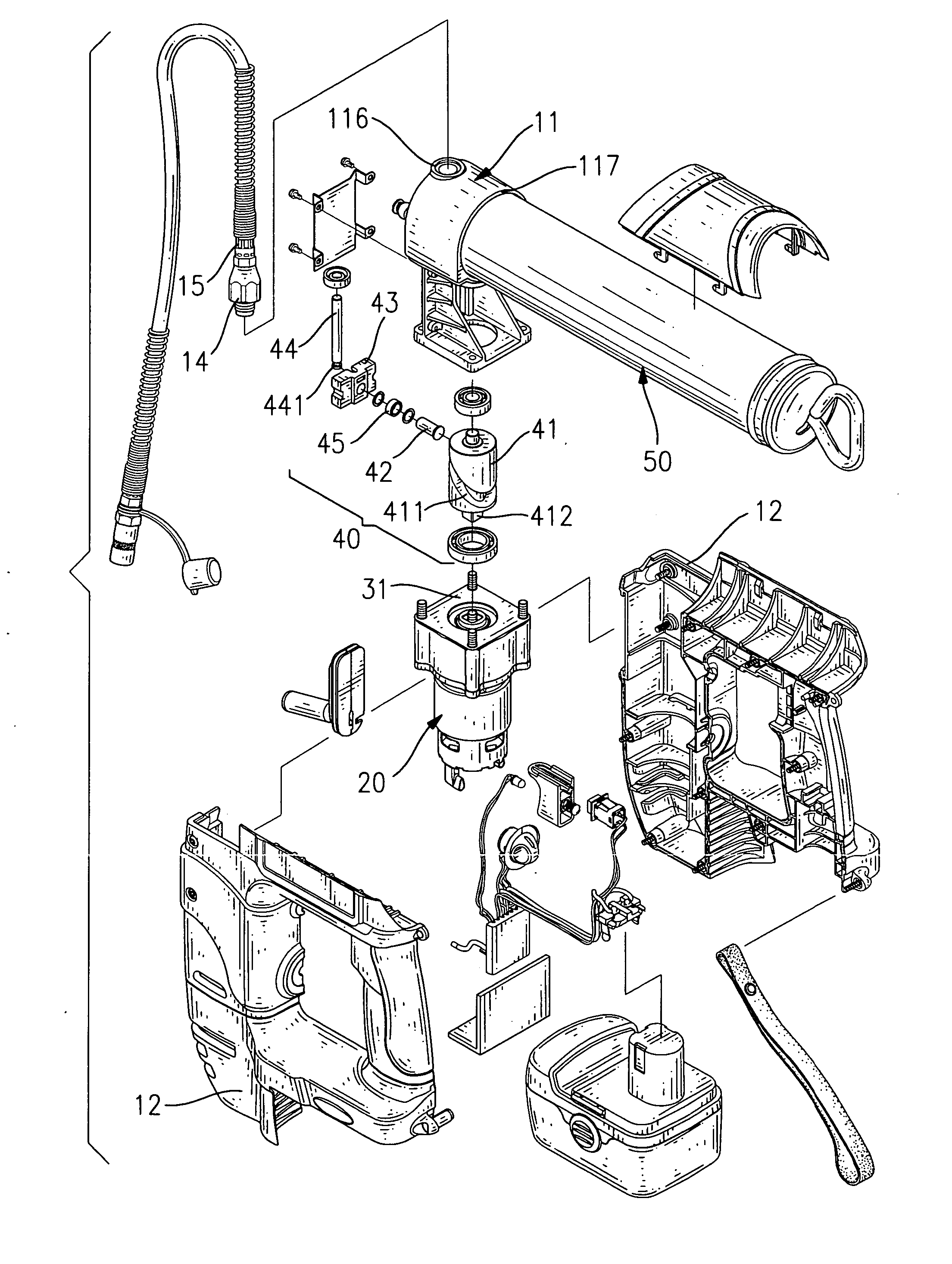
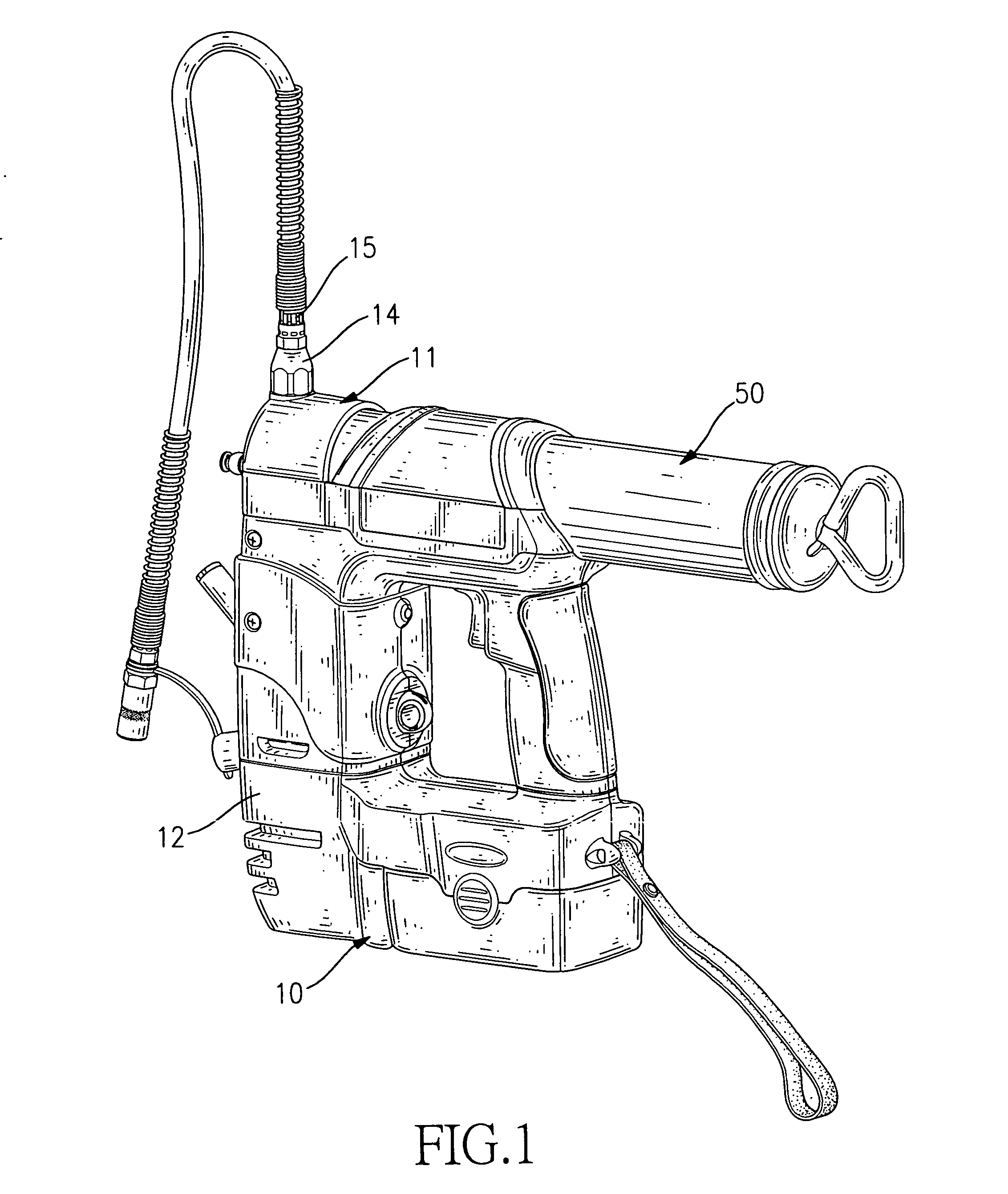
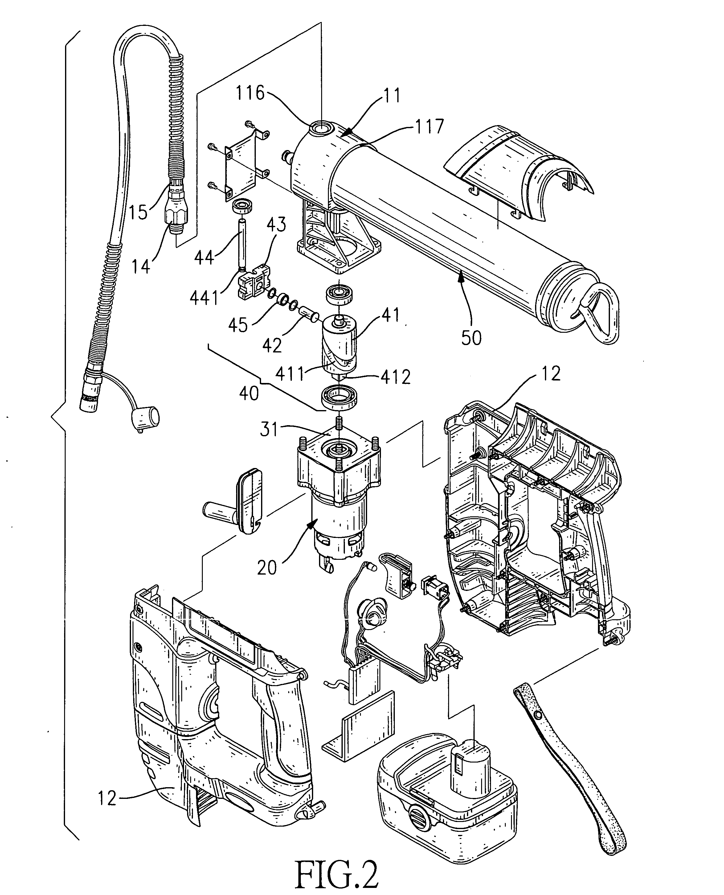
[0022] With reference to FIGS. 1 and 2, a cam-driven pump mechanism in accordance with present invention is used in a battery-powered grease gun (not numbered). The battery-powered grease gun has a body (10), a cartridge holder (50) and a cam-driven pump mechanism. The body (10) comprises a casing (12) and a discharge assembly (not numbered).

[0023] With further reference to FIG. 4, the casing (12) comprises two half shells (not numbered) and has a top (not numbered) and an inner chamber (121) formed when the half shells connect to each other.

[0024] The discharge assembly is mounted on the top of the casing (12) and comprises a transition body (11), a ball check valve (14) and a discharge adapter (15). The transition body (11) has a top (not numbered), a bottom (not numbered), an inward side (not numbered), an outward side (not numbered), a grease channel (110), a ball check valve housing (116) and a cartridge connector (117).

[0025] The grease channel (110) is formed longitudinall...


PUM


Abstract

A cam-driven pump mechanism for a battery-powered grease gun includes a cam driver and a cam-driven pump. The grease gun has a transition body having a grease channel and a casing having an inner chamber. The cam driver is mounted in the inner chamber. The cam-driven pump has a cylindrical cam, a sliding block, a follower and a piston. The cylindrical cam is rotatably mounted in the inner chamber, is rotated by the cam driver and has an eccentric annular groove. The sliding block is slidably mounted in the casing. The follower is securely attached to the sliding block and mounted slidably in the eccentric annular groove. The piston is mounted slidably in the grease channel and connects to the sliding block. Consequently, use of the cylindrical cam prevents localized friction on the sliding block and keeps the pump mechanism from wearing excessively.

Description

BACKGROUND OF THE INVENTION [0001] 1. Field of the Invention [0002] The present invention relates to a battery-powered grease gun, and more particularly to a battery-powered grease gun that uses a cylindrical cam to drive a pump mechanism to continuously discharge grease from the grease gun. [0003] 2. Description of Related Art [0004] With reference to FIGS. 5 and 6, a conventional battery-powered grease gun has a body (60) and a pump assembly (not numbered). The pump assembly is mounted in the body (60) and comprises a motor (64), a planetary gear assembly (65), a drive disk (66), a drive pin (67), a sliding block (68), a piston (69) and a transition body (61) with a drive channel (not numbered). [0005] The body (60) has a grease channel (601), connects to a cylindrical lubricant cartridge holder (602) and comprises a ball check valve (62) and a discharge spout (63). The discharge spout (63) communicates with the grease channel (601). The ball check valve (62) is mounted between th...

Claims


Application Information

Patent Timeline
Patent Type & Authority Applications(United States)
IPC IPC(8): F04B17/00F04B19/02F04B35/04
CPCF04B19/027
Inventor HUANG, SAN-IYEH, HAO-JUNG
Owner TECHWAY INDAL
Learn More