Device for controlling parasitic losses in a fluid pump
- Summary
- Abstract
- Description
- Claims
- Application Information
AI Technical Summary
Benefits of technology
Problems solved by technology
Method used
Image

Examples
Embodiment Construction
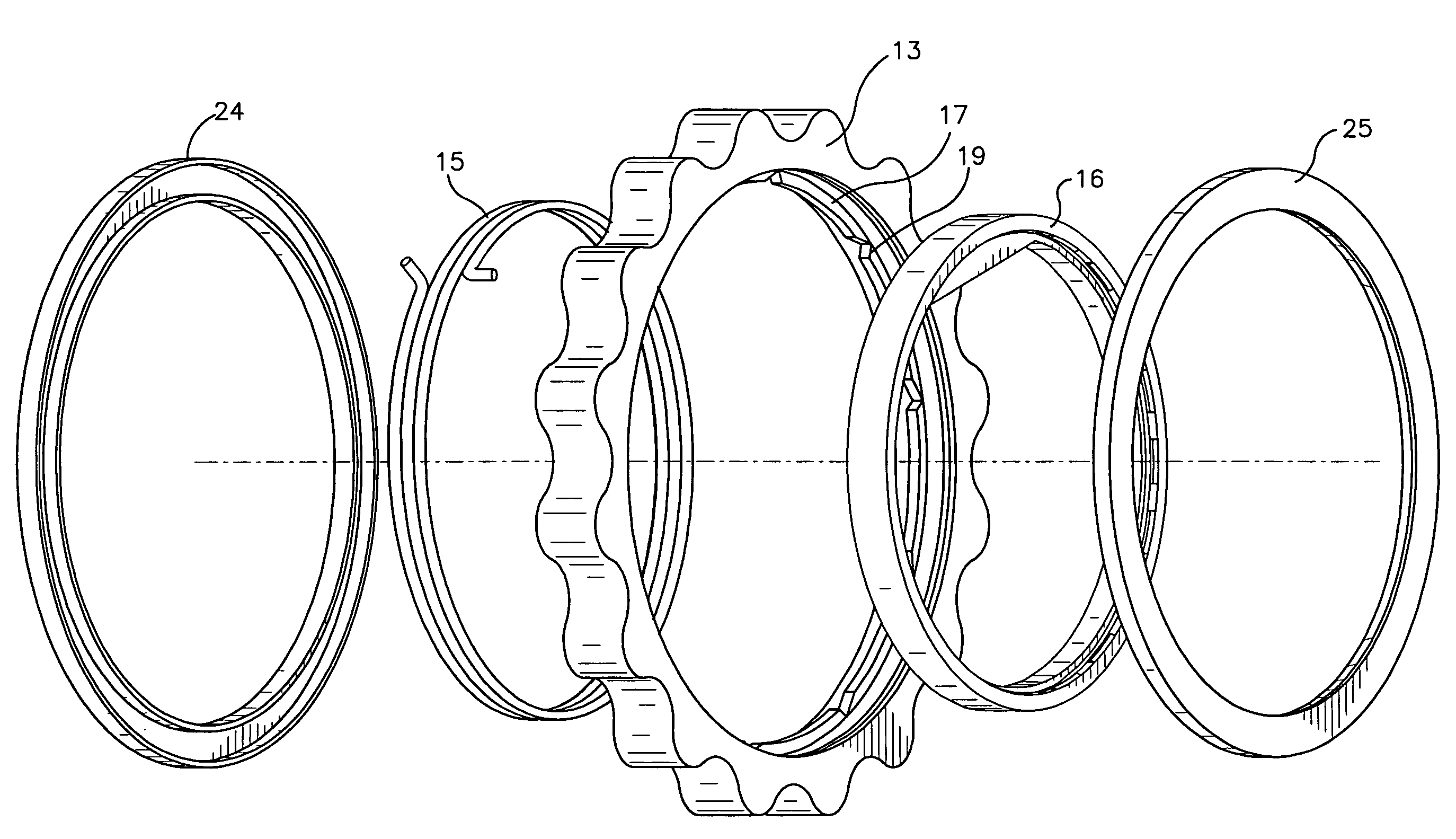
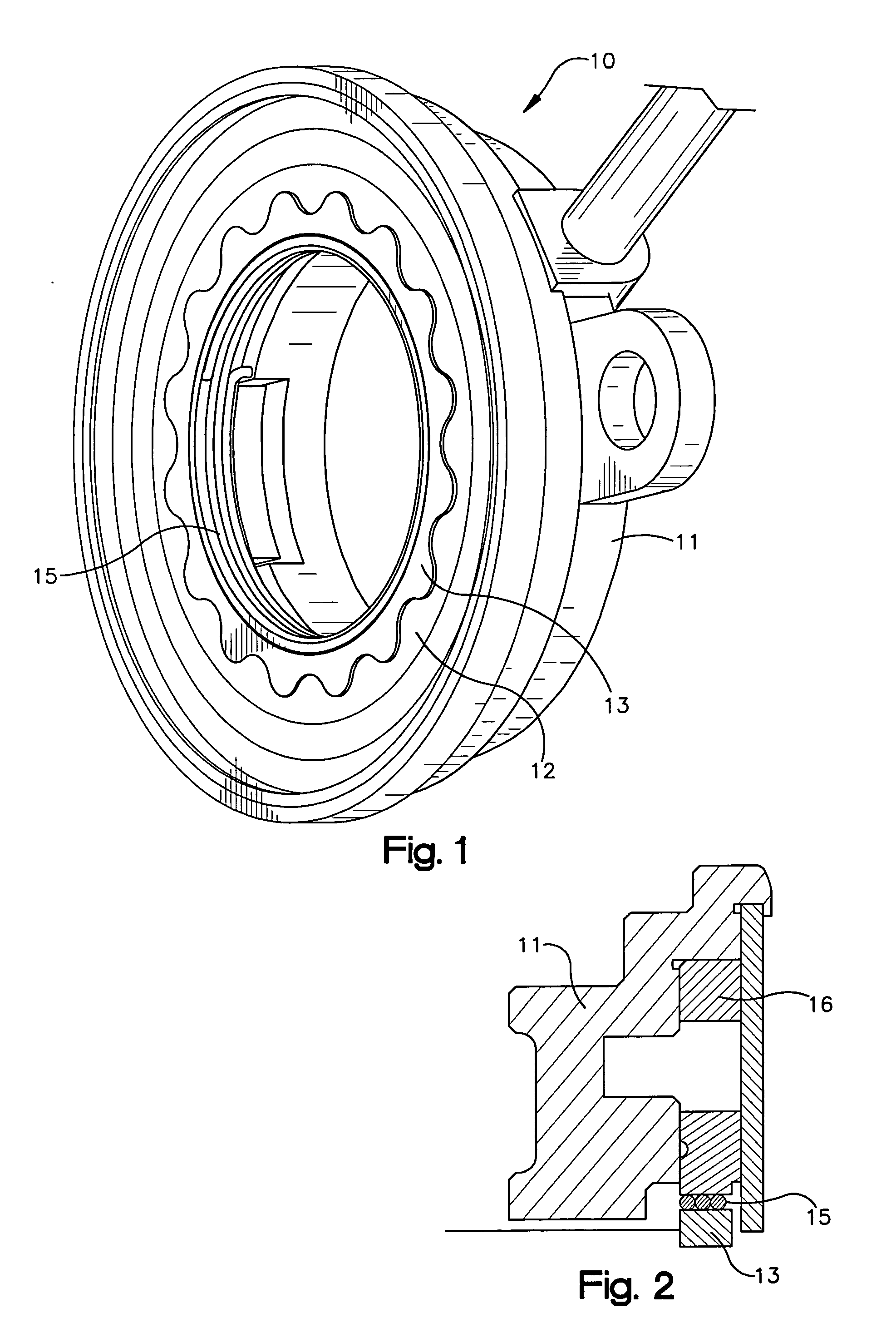
[0018] The present invention will now be described in accordance with the preferred embodiment as shown in FIGS. 1 through 6. An oil pump assembly 10 generally comprises a pump housing 11, a driven pumping element 12, a drive pumping element 13, and a clutch element 15. Power is input into the oil pump assembly 10 by a driveshaft connected to the engine to provide power while the engine is running.
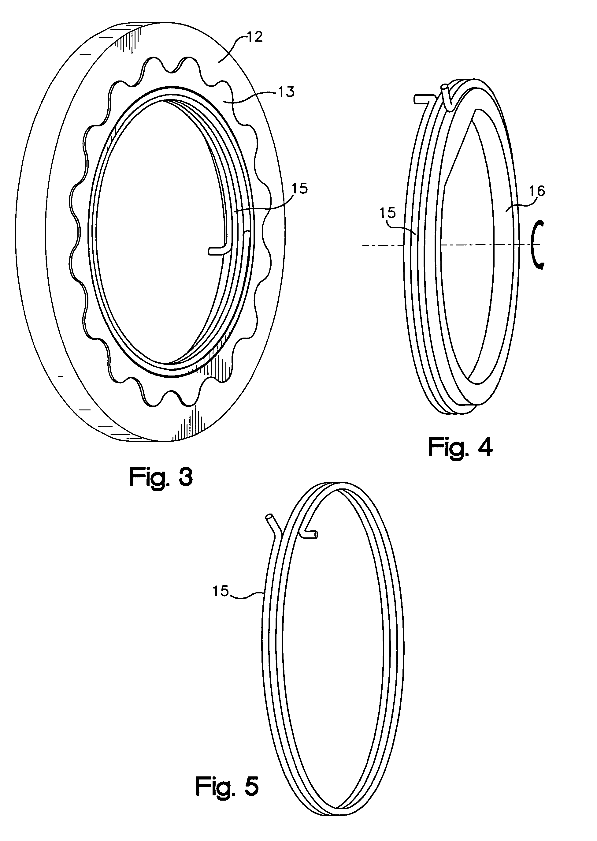
[0019] The input power driveshaft (not shown) can either be connected to a clutch hub 16, as shown in FIG. 4, which frictionally engages the clutch element 15 or the driveshaft can directly frictionally engage the clutch element 15 as provided in FIG. 3. For the purposes of this disclosure and the claims, the driveshaft and any element connected to the driveshaft that frictionally engages the clutch element will be referred to as the driveshaft.
[0020] As viewed in FIG. 4, the driveshaft is driven in a clockwise fashion and frictionally engages the clutch element 15 so as to tighten the c...
PUM
 Abstract
Description
Claims
Application Information