Film forming apparatus and method

a film forming and film technology, applied in the direction of chemically reactive gases, coatings, crystal growth processes, etc., can solve the problems of inferior uniformity of in-plane deposit amount and composition ratio, less stability, and inability to employ conventionally used siosub>2 /sub>films for such advanced devices, etc., to achieve the uniformity of in-plane ald films thus formed. , the effect of improving the uniformity

Inactive Publication Date: 2005-11-10
RENESAS TECH CORP
View PDF7 Cites 391 Cited by
  • Summary
  • Abstract
  • Description
  • Claims
  • Application Information

AI Technical Summary

Benefits of technology

[0012] This invention has been made in order to solve the above-noted problems faced with the ALD film formation apparatus and method using a plurality of film-forming raw materials, and its object is to provide an improved film formation method and apparatus capable of ameliorating the in-plane uniformity of an ALD film thus formed.

Problems solved by technology

One of important issues for the scaling of complementary metal oxide semiconductor (CMOS) devices in near future is to improve transistor characteristics while at the same time thinning gate insulating dielectric films.
Unfortunately, it seems likely that conventionally used SiO2 films are hardly employable for such advanced devices of this generation or later.
As apparent from FIGS. 9A-9C, this prior art method suffers from problems which follow: the resultant film layer is inferior in uniformities of the in-plane deposit amount and composition ratio, and also less in stability.
The decomposition badly behaves to change the quality of a desired film on the wafer in some cases or create a large number of particles in other cases.
Another disadvantage of the prior art is as follows.
This causes baneful influences, such as pipe blockage, unwanted particle creation and others.
A further disadvantage faced with the prior art is as follows.
Frequent execution of joint lock / unlock operations upon opening and closing of the chamber lid would cause accidental gas leakage at such portions.

Method used


Image

  • Film forming apparatus and method
  • Film forming apparatus and method
  • Film forming apparatus and method

Examples


first embodiment

Film Forming Apparatus

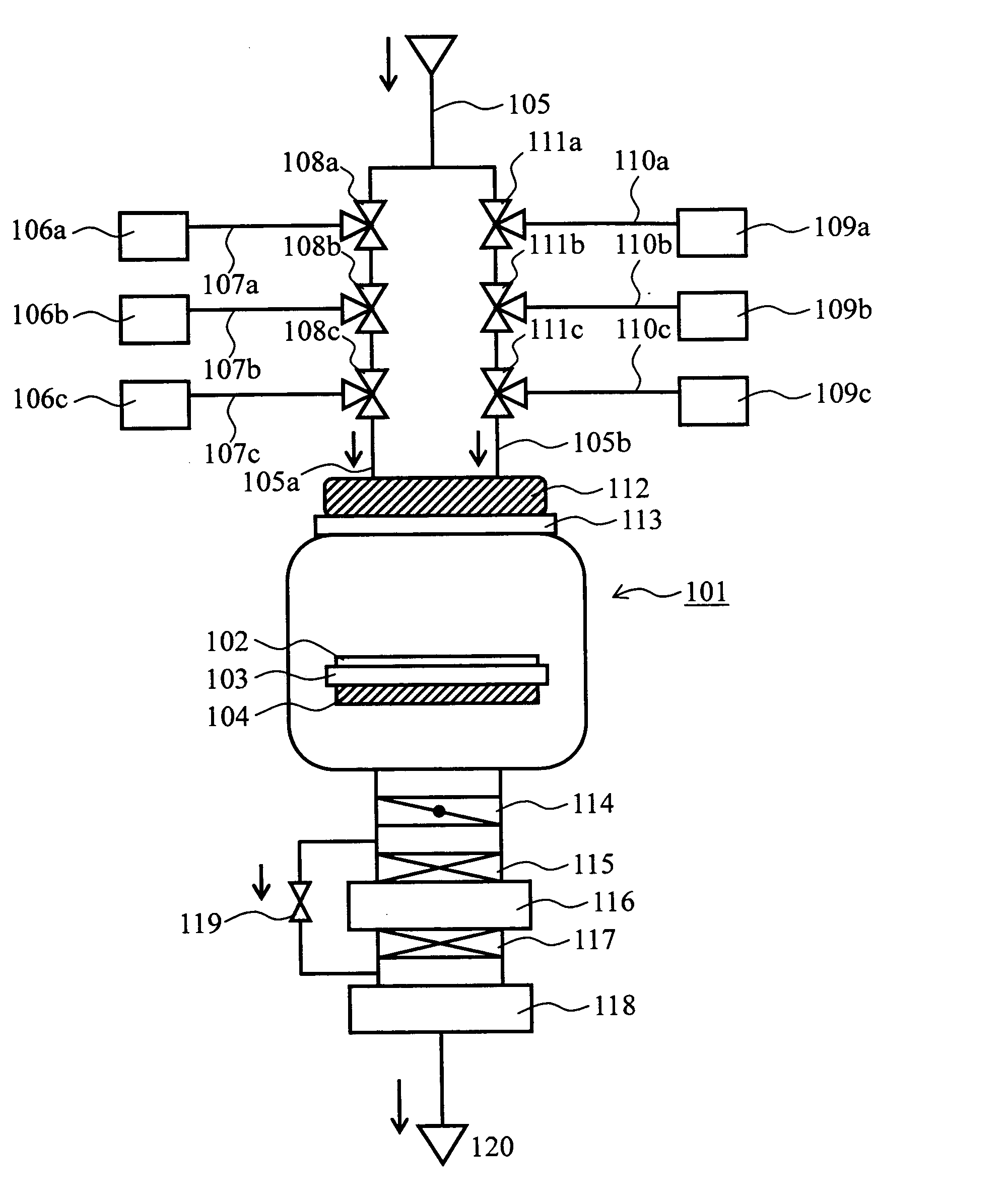
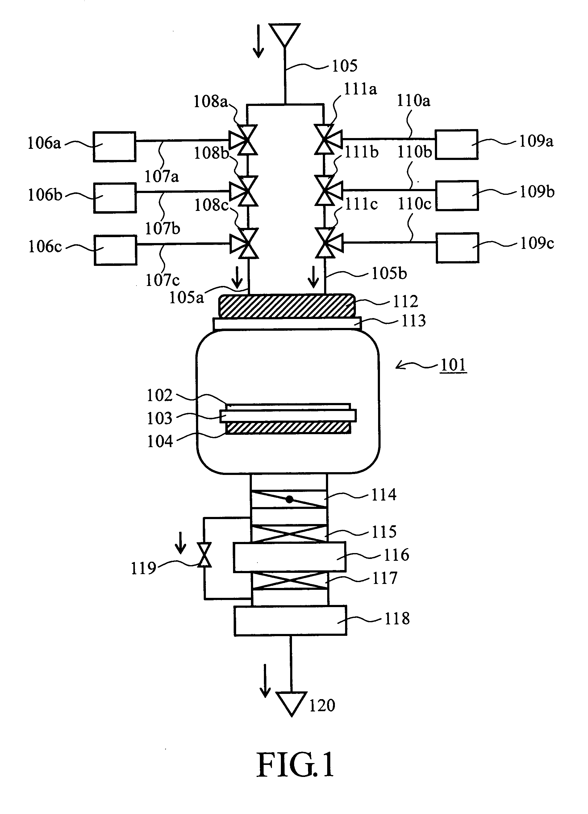
[0027] A first embodiment of the present invention will now be explained below. This embodiment is arranged so that a main carrier gas supplying pipe is split or “branched” to provide a couple of parallel gas flow paths. Directly coupled to these branched main carrier gas supply pipes—say, branch pipes—are those pipes which are extended from a plurality of film-forming raw material supply units or “sources” and film formation assistant supply sources. Using such pipe structure is aimed at preclusion of mutual contact of different kinds of raw materials and assistants prior to the introduction into the main carrier gas supply pipe.

[0028] More specifically, the film forming apparatus embodying the invention may be an atomic layer deposition (ALD) film formation equipment which includes a disperser, a susceptor, and a heat module. The disperser may be a shower plate. A main carrier gas is slit into two gas flows, which are guided to pass through the shower plate...

second embodiment

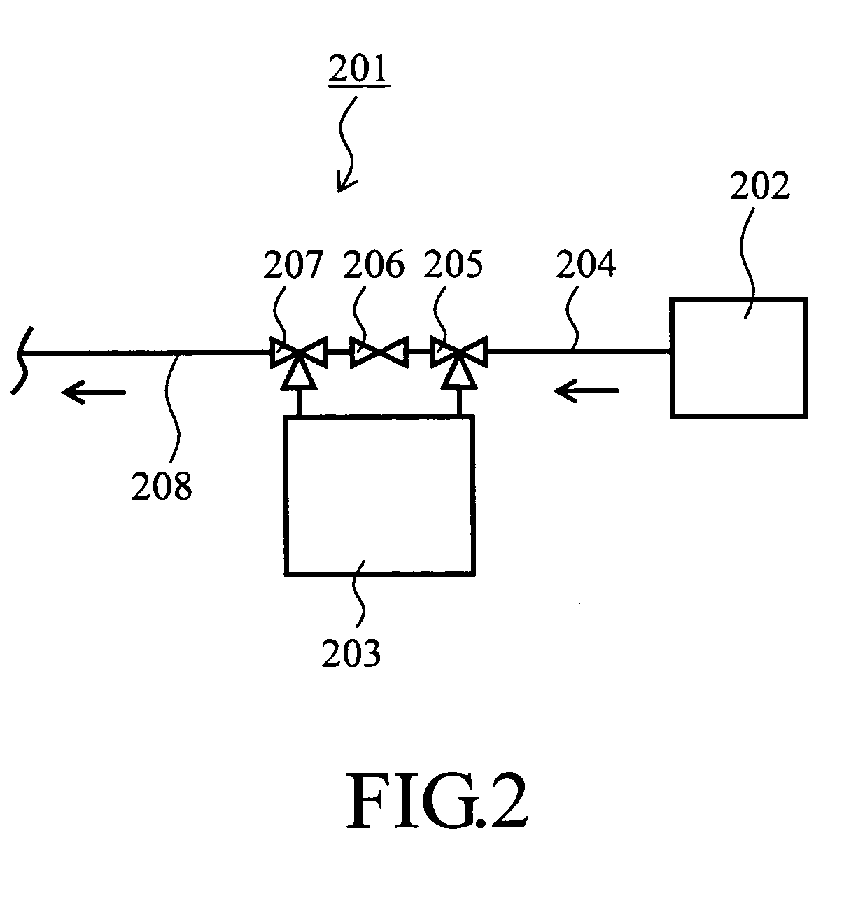
[0052] This embodiment is aimed at elimination of a need for supplying to the ALD reactor 101 those gases that are altered in quality due to continuous residence in flowpath lines. To this end, a ventilation tube (vent line) is further added to more than one pipe which supplies either a film-forming raw material or assistant to the main carrier gas supply pipe 105 and which extends up to a three-way valve associated therewith. By letting a carrier gas continuously flow in this ventilation pipe system, any gas residing in a raw material / assistant supply pipe may be exhausted without experiencing mixture with other gases while no film formation is being performed. This eliminates unwanted supplying of any quality-altered gas residing in the supply line to the ALD reactor.

[0053] A film forming apparatus of this embodiment will be explained with reference to FIG. 3, which depicts its cross-sectional view. In FIG. 3, the members similar in function to those of the above-noted apparatus ...

third embodiment

[0061] This embodiment is arranged so that the main carrier gas supply pipe 105 of FIG. 1 is divided into an increased number of parallel branch pipes, which number is equal to a total number of different kinds of film-forming raw materials and assistant chemicals used. Respective branch pipes are capable of supplying different raw materials and assistants through three-way valves as provided therein independently of one another. This multiple branch pipe system almost completely avoids the risk that more than two of the different raw materials and assistants (i.e. oxidants or reducers) must pass through an identical or common pipe system upon introduction into the ALD film forming reactor, thereby further improving the uniformity of a thin-film layer thus formed.

[0062] An explanation will be given of a film forming apparatus of this embodiment with reference to FIG. 5, which is a pictorial representation of the apparatus. In FIG. 5, the same parts or components as those in the app...


PUM

PropertyMeasurementUnit
equivalent oxide thicknessaaaaaaaaaa
total timeaaaaaaaaaa
vapor pressureaaaaaaaaaa

Abstract

An atomic layer deposition (ALD) apparatus capable of forming a conformal ultrathin-film layer with enhanced step coverage is disclosed. The apparatus includes an ALD reactor supporting therein a wafer, and a main pipe coupled thereto for constant supply of a carrier gas. This pipe has two parallel branch pipes. Raw material sources are connected by three-way valves to one branch pipe through separate pipes, respectively. Similarly, oxidant / reducer sources are coupled by three-way valves to the other branch pipe via independent pipes. ALD works by introducing one reactant gas at a time into the reactor while being combined with the carrier gas. The gas is “chemisorped” onto the wafer surface, creating a monolayer deposited. During the supply of a presently selected material gas from its source to a corresponding branch pipe, this gas passes through its own pipe independently of the others. An ALD method is also disclosed.

Description

TECHNICAL FIELD [0001] The present invention relates generally to a film-forming apparatus adaptable for use in the manufacture of semiconductor devices or else. More particularly but not exclusively, this invention relates to a film formation apparatus of the type relying upon atomic layer deposition (ALD) technology and having an improved raw material supplying system. The invention also relates to a method of forming a thin-film layer by using the apparatus. BACKGROUND OF THE INVENTION [0002] One of important issues for the scaling of complementary metal oxide semiconductor (CMOS) devices in near future is to improve transistor characteristics while at the same time thinning gate insulating dielectric films. According to the update version of an article titled “International Technology Roadmap for Semiconductors (ITRS) 2002,” 65-nanometer (nm) technology node generation devices with mass production expected to begin in 2005 are required to accomplish 1.2 to 1.6 nm in equivalent o...

Claims


Application Information

Patent Timeline
Patent Type & Authority Applications(United States)
IPC IPC(8): C23C16/44C23C16/455C30B25/14H01L21/31H01L21/316H01L21/8238H01L27/092H01L29/78
CPCC23C16/45514C23C16/45531C30B25/14C23C16/45561C23C16/45544
Inventor KAWAHARA, TAKAAKITORII, KAZUYOSHI
Owner RENESAS TECH CORP
Why Eureka
Try Eureka