
Press-fit terminal and circuit board module using the same

Inactive Publication Date: 2005-11-10
YAZAKI CORP
View PDF3 Cites 25 Cited by
  • Summary
  • Abstract
  • Description
  • Claims
  • Application Information

AI Technical Summary

Benefits of technology

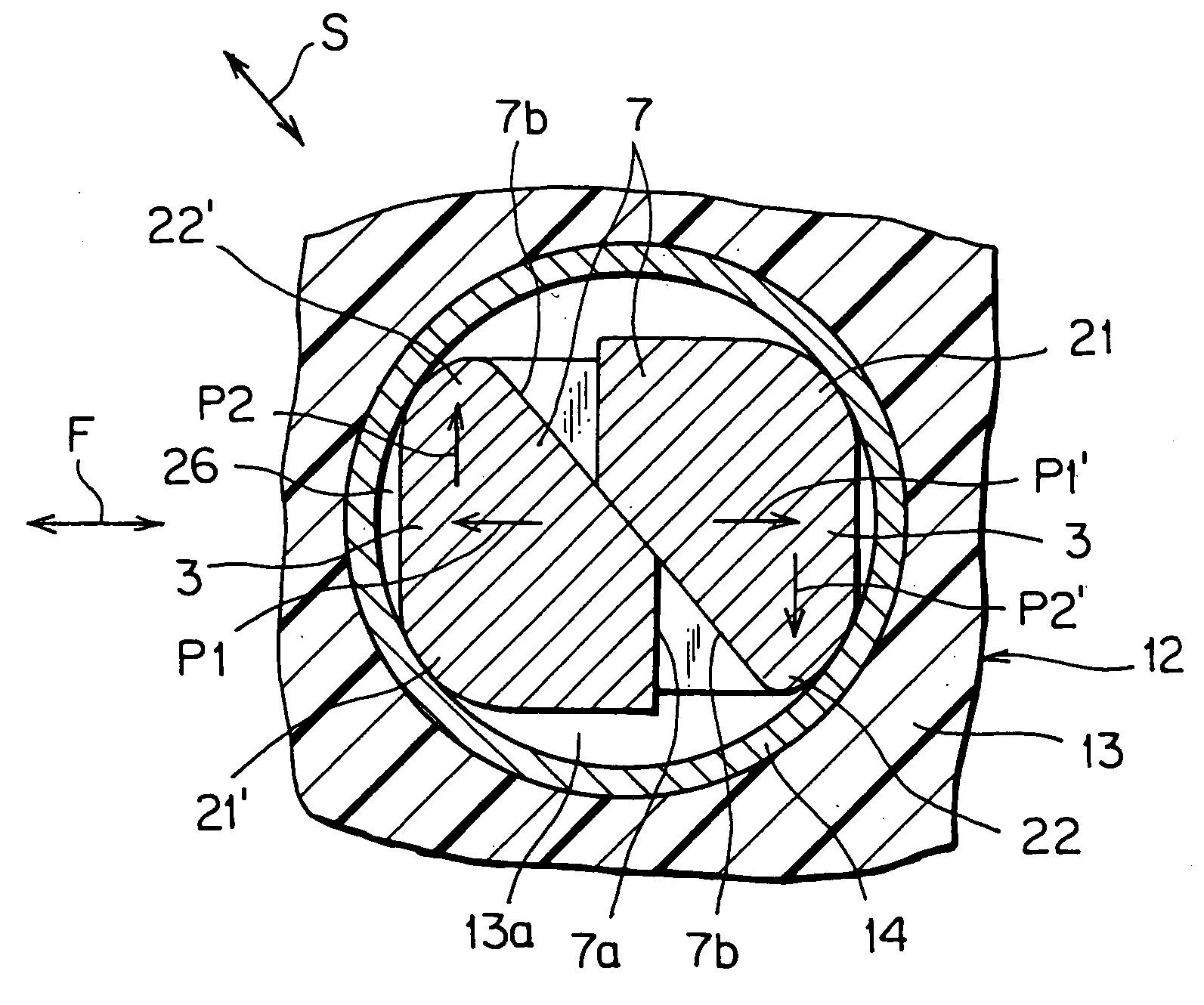
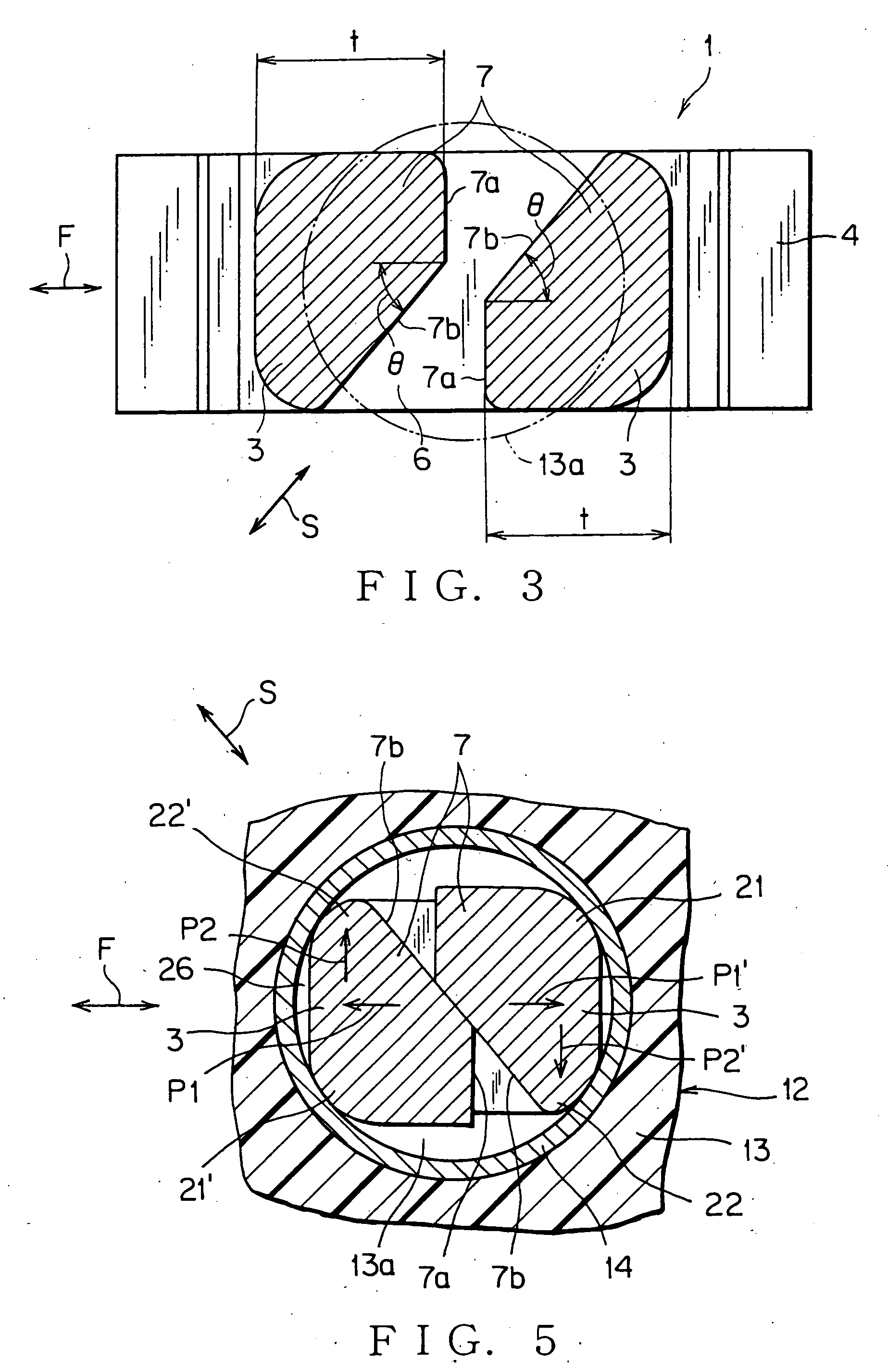
[0018] According to the above, the pair of the resilient contacts can be resiliently deformed in two directions. Therefore, in comparison with the resilient contacts deformed in only one of direction, a total amount of deformation of the resilient contacts deformed in two directions can be large. Therefore, even if the pair of the resilient contacts is formed thick for improving terminal holding force, and resultingly the deformation space becomes narrower, the pair of the resilient contacts is pressed into the through-hole without improving press-fit force. Further, the pair of the resilient contacts firmly contacts with the inner wall of the through-hole, with a sum of recovery force in two directions. Therefore, electric contact reliability is improved. Here, the press-fit force is defined as pressing force to press the press-fit terminal in an axial direction thereof. The terminal holding force is defined as holding force to hold the press-fit terminal with external force received from the inner wall of the through-hole.
[0028] According to the above, a plurality of press-fit terminals are collectively held in the connector housing. Thereby, the slim press-fit terminals are reinforced with the connector housing, and prevented from being short-circuited each other. Further, mounting the connector housing holding the press-fit terminals on the circuit board improves connection workability between the circuit board and the press-fit terminals.

Problems solved by technology

Therefore, even if the pair of the resilient contacts is formed thick for improving terminal holding force, and resultingly the deformation space becomes narrower, the pair of the resilient contacts is pressed into the through-hole without improving press-fit force.

Method used


Image

  • Press-fit terminal and circuit board module using the same
  • Press-fit terminal and circuit board module using the same
  • Press-fit terminal and circuit board module using the same

Examples


first embodiment

of the Present Invention

[0046] A first embodiment of a press-fit terminal according to the present invention will be described below with reference to FIGS. 1 to 5.

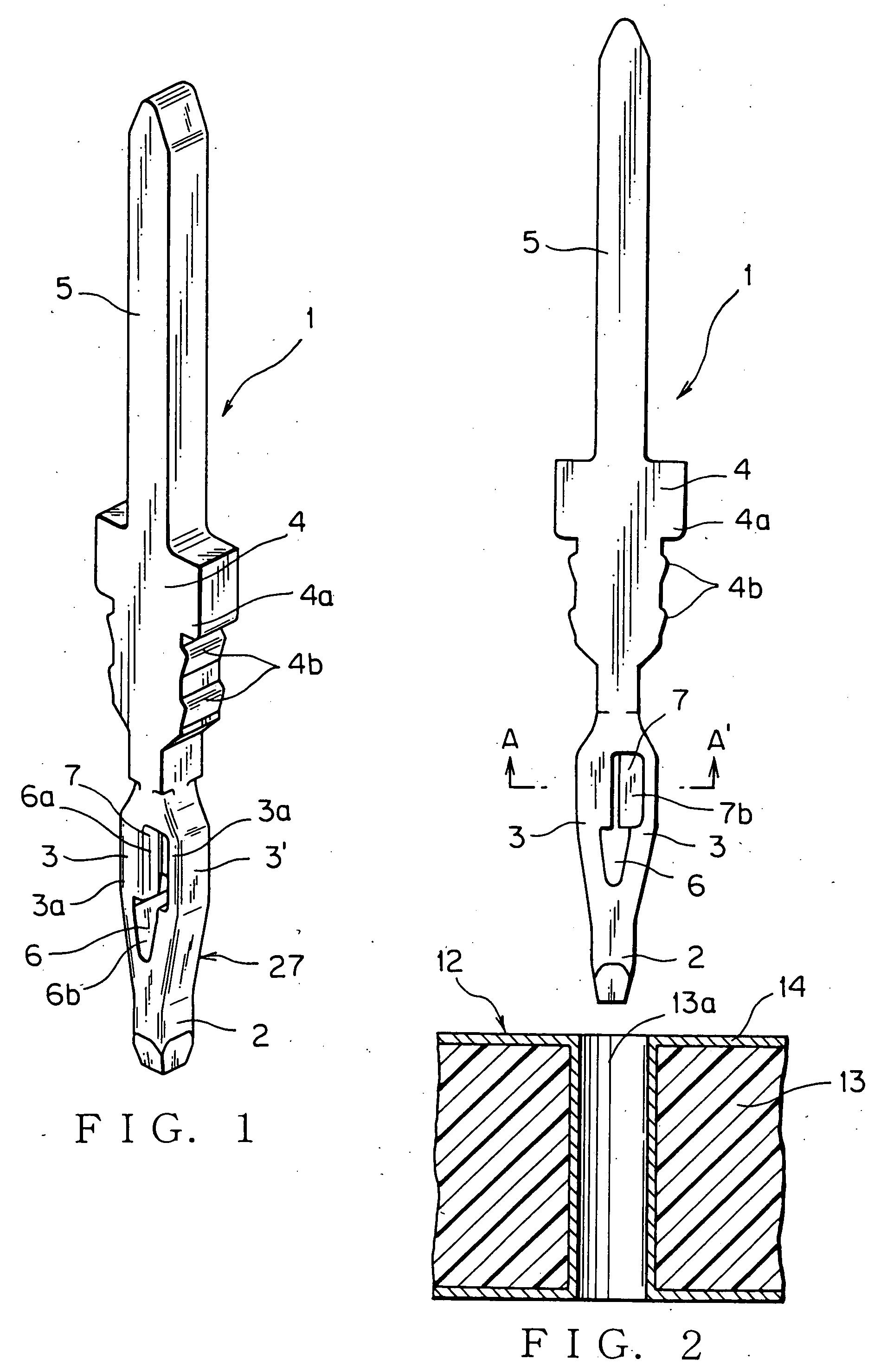
[0047] A press-fit terminal 1 of the first embodiment is formed in a strip shape by stamping a conductive substrate made of such as copper-alloy. The press-fit terminal 1 includes: an introducing portion 2 to be inserted into a through-hole 13a of a circuit board 12 (FIG. 2); a pair of resilient contacts 3 continued to the introducing portion 2 and being swelled; a substrate-press-fit portion 27 having the introducing portion 2 and the resilient contacts 3; a housing-press-fit portion 4 continued to the resilient contacts 3 to be pressed into a connector housing 16 (FIG. 4); and a tabular electric contact 5 continued to the housing-press-fit portion 4.

[0048] A direct mounting connector 15 includes the connector housing 16 made of resin, and a plurality of press-fit terminals 1 pressed into the connector housing 16. As s...

second embodiment

of the Present Invention

[0064] A second embodiment of a press-fit terminal according to the present invention will be described below with reference to FIGS. 6 to 13. In order to avoid repetitions, identical elements will be designated by identical reference numerals and only the differences existing in comparison with the first embodiment will be explained.

[0065] As shown in FIG. 9, a pair of resilient contacts 10 of a press-fit terminal 1A includes a substantially V section perpendicular to an axis of the press-fit terminal 1A. As shown in FIG. 6, a press-fit portion 28 of the press-fit terminal 1A includes an introducing portion 2 and the resilient contacts 10.

[0066] As shown in FIG. 9, each of the resilient contacts 10 has a substantially semi-circular section perpendicular to a longitudinal direction along a length of each resilient contact 10. As shown in FIG. 8, an aperture angle η is defined as an angle between inner flat walls of the resilient contacts 10. A value of the ...


PUM


Abstract

A press-fit terminal includes a pair of the resilient contacts being swelled outward, and having a deformation space into which the resilient contacts are deformed. The press-fit terminal is electrically connected to a conductive inner wall of a through-hole on a circuit board by pressing the press-fit terminal into the through-hole. The press-fit terminal includes abutting portions on each inner wall of the pair of the resilient contacts. When the abutting portions abut on each other, the abutting portions regulate deformation of the resilient contacts in a narrowing direction to narrow the deformation space. Then inclined walls formed on the abutting portions induce the resilient contacts to slide on the inclined walls in a direction to separate the resilient contacts from each other.

Description

BACKGROUND OF THE INVENTION [0001] The priority application claims priority of Japanese Patent Application No. 2004-355045, which is hereby incorporated by reference. FIELD OF THE INVENTION [0002] This invention relates to a press-fit terminal for being pressed into a through-hole and electrically contacting a conductive member formed on an inner wall of the through hole, and a circuit board using the press-fit terminal. DESCRIPTION OF THE RELATED ART [0003] Generally, a through-hole into which a press-fit terminal is inserted is formed on a printed circuit board. The press-fit terminal includes a press-fit portion to be mechanically held in the through-hole. One embodiment of the press-fit terminal is disclosed Japanese Patent Application Document JP-A, H05-114427 (Page 2, and FIG. 5), and shown in FIG. 14. [0004] The press-fit terminal 50 is formed by press molding and made of such as copper-alloy, aluminum-alloy and the like. The press-fit portion 52 is positioned between an intr...

Claims


Application Information

Patent Timeline
IPC IPC(8): H01R9/16H01R12/58H01R13/42
CPCH01R12/585
Inventor MATSUMURA, KAORUTANAKA, SHIGERU
Owner YAZAKI CORP
Learn More