

Endoscopic instrument having reduced diameter flexible shaft
a flexible shaft and endoscope technology, applied in the field of endoscopes, guidewires, retrieval devices, can solve the problems of high maintenance costs, easy wear and tear of endoscopes, uncomfortable and upsetting experiences for patients, etc., and achieve the effects of less invasiveness, less traumatic, and small size and flexibility
- Summary
- Abstract
- Description
- Claims
- Application Information
AI Technical Summary
Benefits of technology
Problems solved by technology
Method used
Image

Examples
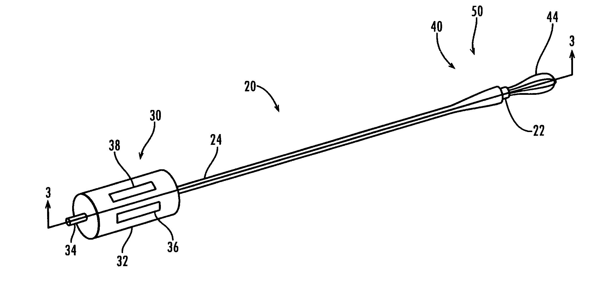
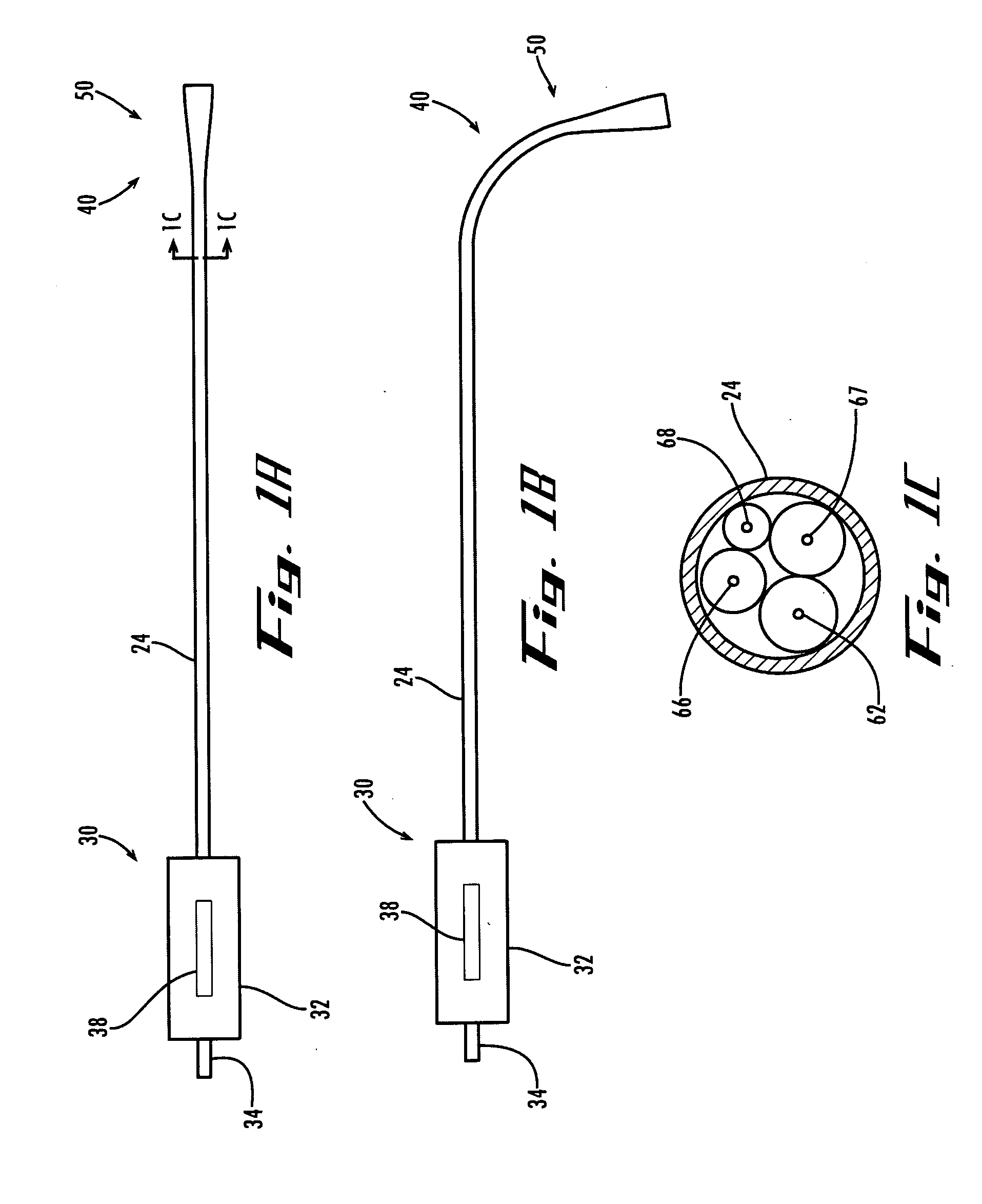
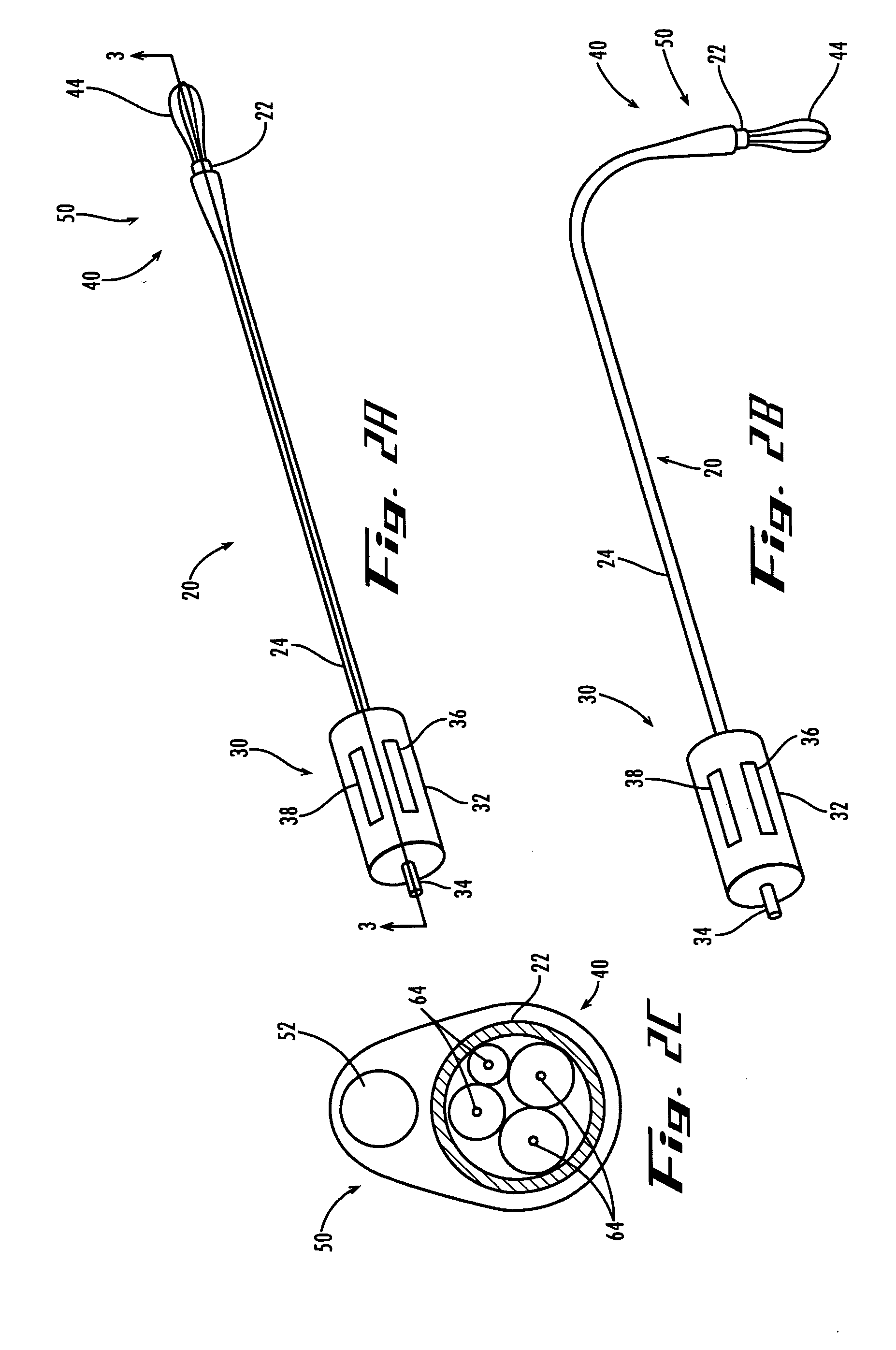
shaft embodiments
[0090]FIGS. 4A and 4B depict a shaft embodiment comprising a filament core 60, a jacket 28, and a sheath 24 slideably disposed over jacket 28. Jacket 28 is a thin-walled tube-like covering that forms an exterior wall of filament core 60 to bind core 60 into a substantially tight assembly, and provide a supporting structure for imaging system 50 and other distal components of endoscopic instrument 20. Filaments at the outer perimeter of core 60 contact the inner wall of jacket 28, and adjacent filaments contact each other lengthwise along shaft 22, so that core 60 is bundle within jacket 28. Because many filaments have hard, fixed cross-sectional profiles, filaments that are pressed into contact may nonetheless leave open spaces or interstices among themselves. Typically, such gaps run lengthwise within core 60, as best shown in cross-section in FIG. 4B.
[0091] Sleeve 24 is a tube-like structure tightly over jacket 28. Outer wall of jacket 28 slides longitudinally within sheath 24. A...
PUM
 Abstract
Description
Claims
Application Information