Multiple lumen sensor attachment

a sensor and multi-lumen technology, applied in the field of two-piece cranial bolts, to achieve the effect of increasing the amount of torqu

Active Publication Date: 2005-11-10
INTEGRA LIFESCI
View PDF50 Cites 73 Cited by
  • Summary
  • Abstract
  • Description
  • Claims
  • Application Information

AI Technical Summary

Benefits of technology

[0015] An embodiment includes a wing engagement portion disposed on a top surface of the threaded portion (the top surface is outside the skull). A wing portion is disposed on an outer surface of the base portion. The wing portion engages the wing engagement portion when the stem portion engages the mating connector. Once engaged, when the base portion is rotated, the threaded portion is rotated along with the base portion. This embodiment permits ease of tightening or loosing of the threaded portion in the skull by rotating just the lumen portion.
[0016] An insertion tool can also be provided that engages the threaded portion and provides mechanical advantage to increase the amount of torque applied to the threaded portion while inserting the threaded portion into the skull. The insertion tool further includes an extending arm that extends from the skull. When its work is completed, the insertion tool can be removed from the threaded portion of the cranial bolt.

Problems solved by technology

However, if the sensors are placed too close to a drainage catheter in the drainage lumen, the sensors will read the stresses and conditions caused by the drainage catheter and not the actual state of the brain.

Method used


Image

  • Multiple lumen sensor attachment
  • Multiple lumen sensor attachment
  • Multiple lumen sensor attachment

Examples


Embodiment Construction

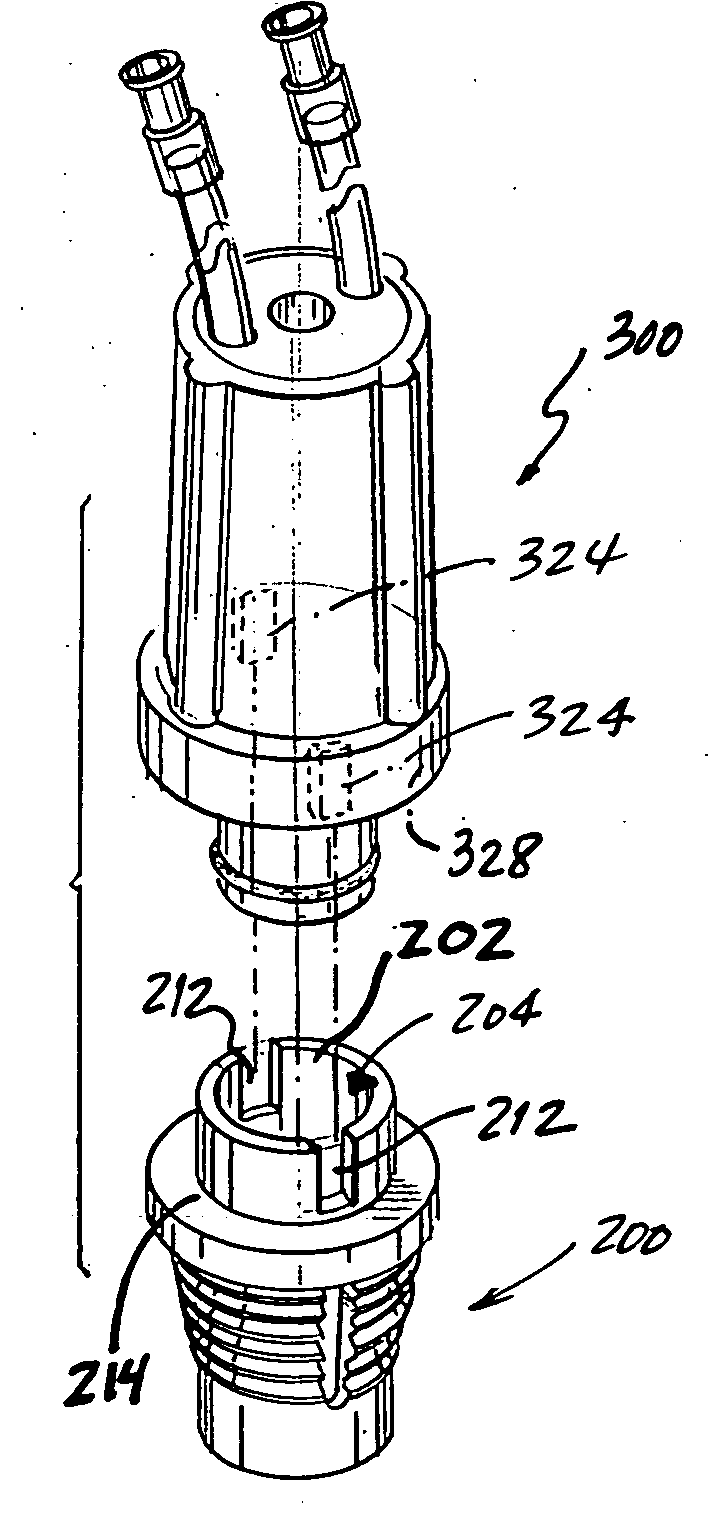
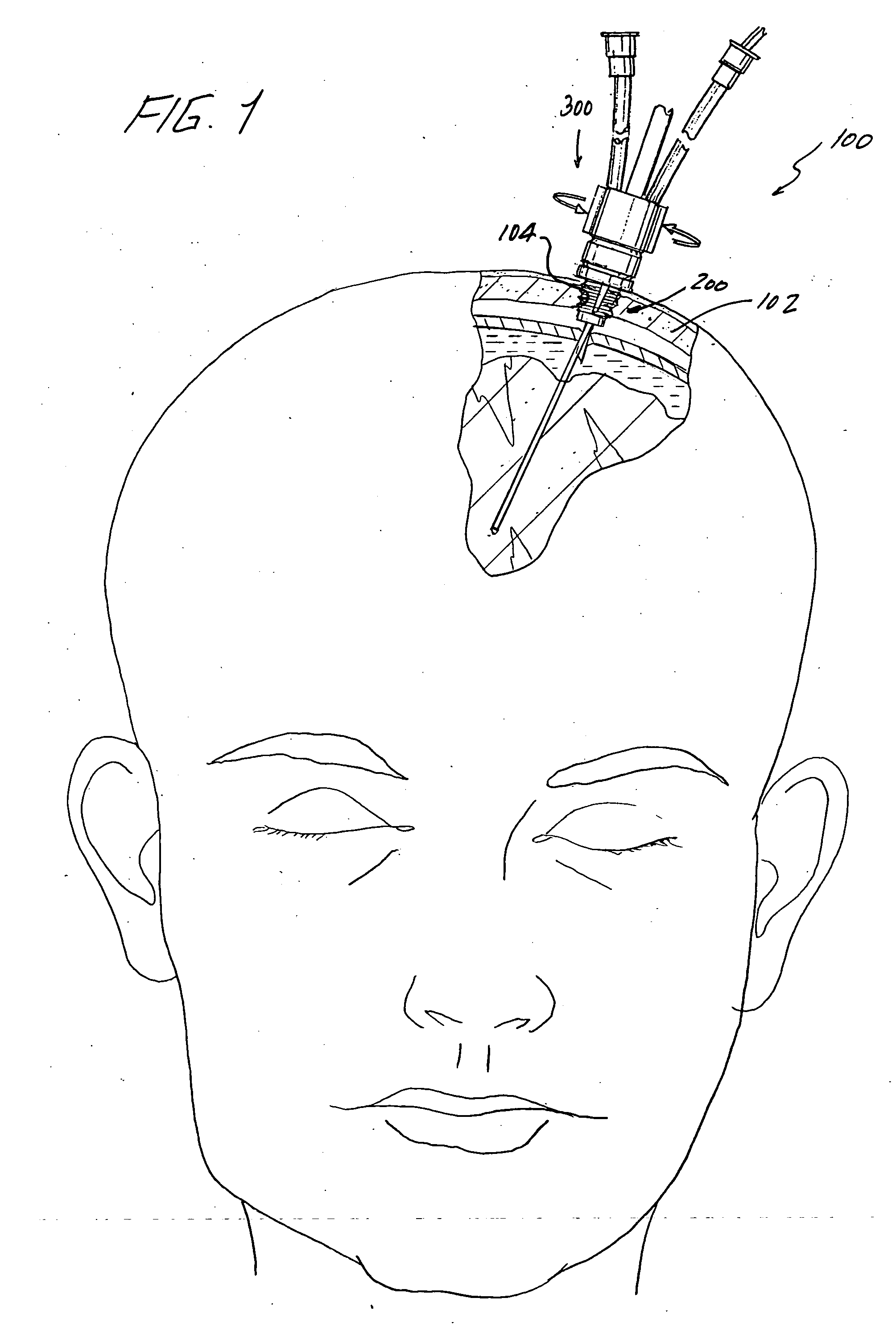
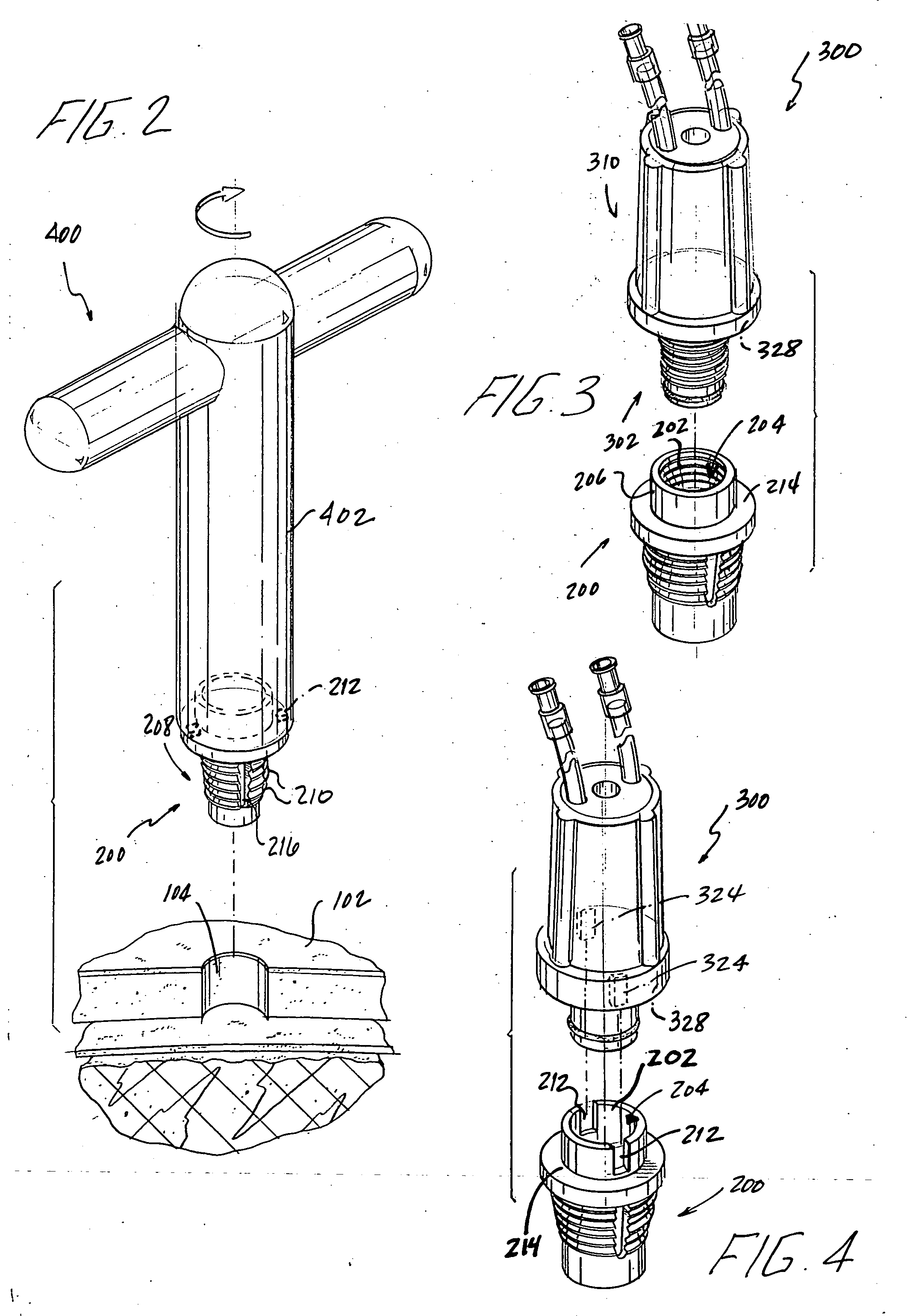
[0033] Referring to FIG. 1, a cranial bolt 100 according to the present invention is illustrated secured to a skull 102 of a patient. Cranial bolt 100 includes a threaded portion 200 and a lumen portion 300. Threaded portion 200 has an inner surface 202 that forms a central passageway 204 (FIGS. 3 and 6). Central passageway 204 extends throughout the threaded portion 200 and is illustrated having a circular cross section, but can be any geometric shape, e.g. triangle, square, and pentagon (not illustrated). Further, central passageway 204 may not have a uniform diameter throughout its length.

[0034] Referring now to FIG. 2, threaded portion 200 also has an outer surface 208 with a plurality of threads 210 for engaging a hole 104 formed in skull 102 to fixedly engage threaded portion 200 to skull 102. Typically, a hole is drilled into a patient's skull using a burr drill and, in one embodiment, hole 104 is tapped, or threaded to provide threads for threaded section 200 to engage the ...


PUM


Abstract

A cranial bolt secured to a skull of a patient includes a threaded portion and a lumen portion. Threaded portion has an inner surface forming a central passageway which extends throughout the threaded portion. The inner surface includes a connector mating with the lumen portion. The threaded portion has an outer surface having a plurality of threads for engaging a hole formed in the patient's skull. The lumen portion includes a stem portion that enters the central passageway and engages the mating connector. A fluid tight seal is formed between the inner surface of the threaded portion and the stem portion. At least two lumens are disposed through the stem portion and the base portion. The lumens have a proximal end opening outside the skull and a distal end opening inside the skull. One embodiment includes sensor lumens diverging from the centerline and another allows lumen portion to rotate independent of threaded portion.

Description

BACKGROUND OF THE INVENTION [0001] 1. Field of the Invention [0002] This invention relates to a two piece cranial bolt having a threaded portion to engage the skull and a lumen portion to engage the threaded portion. [0003] 2. Discussion of the Related Art [0004] For certain medical conditions, such as head trauma, it is necessary to place sensors into the brain of the patient. Many of the prior art devices are designed to penetrate the skull, and be fixed in place to allow for the passage of a sensor probe or catheter to the brain. However, most prior art bolts have one opening that allows for only one probe or catheter to reach the brain through the skull. The prior art devices do not allow for multiple readings at the same location or do not allow for a reading or multiple readings to be taken along with the placement of a catheter to drain pressure building up inside the cranium. These prior art devices require the drilling of multiple holes in a patient's skull or the necessary...

Claims


Application Information

Patent Timeline
Patent Type & Authority Applications(United States)
IPC IPC(8): A61B17/58A61B5/03A61B17/34A61B19/00A61M1/00A61M27/00
CPCA61B5/031A61M2210/0693A61B17/3423A61B19/201A61B2017/3411A61B2017/3419A61B2017/3445A61B2017/3449A61B2017/3466A61B2017/349A61B2019/208A61M27/006A61M39/0247A61M2039/025A61M2039/0264A61M2039/0267A61B17/3403A61B90/11A61B2090/103
Inventor WILSON, STEPHEN F.GORHAN, MICHAEL C.
Owner INTEGRA LIFESCI
Why Eureka
Try Eureka