Guided reamer system for reshaping bone

a reamer and bone technology, applied in bone drill guides, medical science, surgery, etc., can solve the problems of system not anticipating, tool itself obstructing the view of the femoral lobe, etc., to achieve accurate and controlled reshaping of the femoral joint and reduce friction

Inactive Publication Date: 2005-11-10
VIANT AS&O HLDG LLC
View PDF10 Cites 35 Cited by
  • Summary
  • Abstract
  • Description
  • Claims
  • Application Information

AI Technical Summary

Benefits of technology

[0007] A reamer system is provided which includes a cannulated reamer handle, and a corresponding cannulated reamer, which, when assembled and operated over a drill pin secured in a manner axially aligned with the stem of the femoral joint, enables the accurate and controlled reshaping of the femoral joint. The reamer is made up of a cutting form and a central guide, in which the guide is supported at the center of the cutting form by a bar structure. The bar structure includes portions which connect to and extend radially between the central guide and a peripheral edge of the cutting form. Optionally, the central guide includes a surface offset from a plane of the bar...

Problems solved by technology

However, while useful for controlling the cutting of the acetabulum, this system does not foresee a sliding fit between the reamer and the twist drill but rather one in which the two rotate together as a unit.
Other systems provide for reshaping of the...

Method used


Image

  • Guided reamer system for reshaping bone
  • Guided reamer system for reshaping bone
  • Guided reamer system for reshaping bone

Examples


Embodiment Construction

)

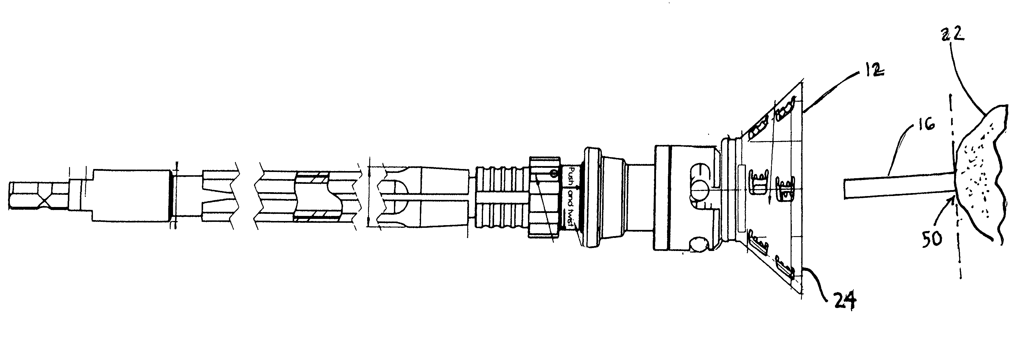
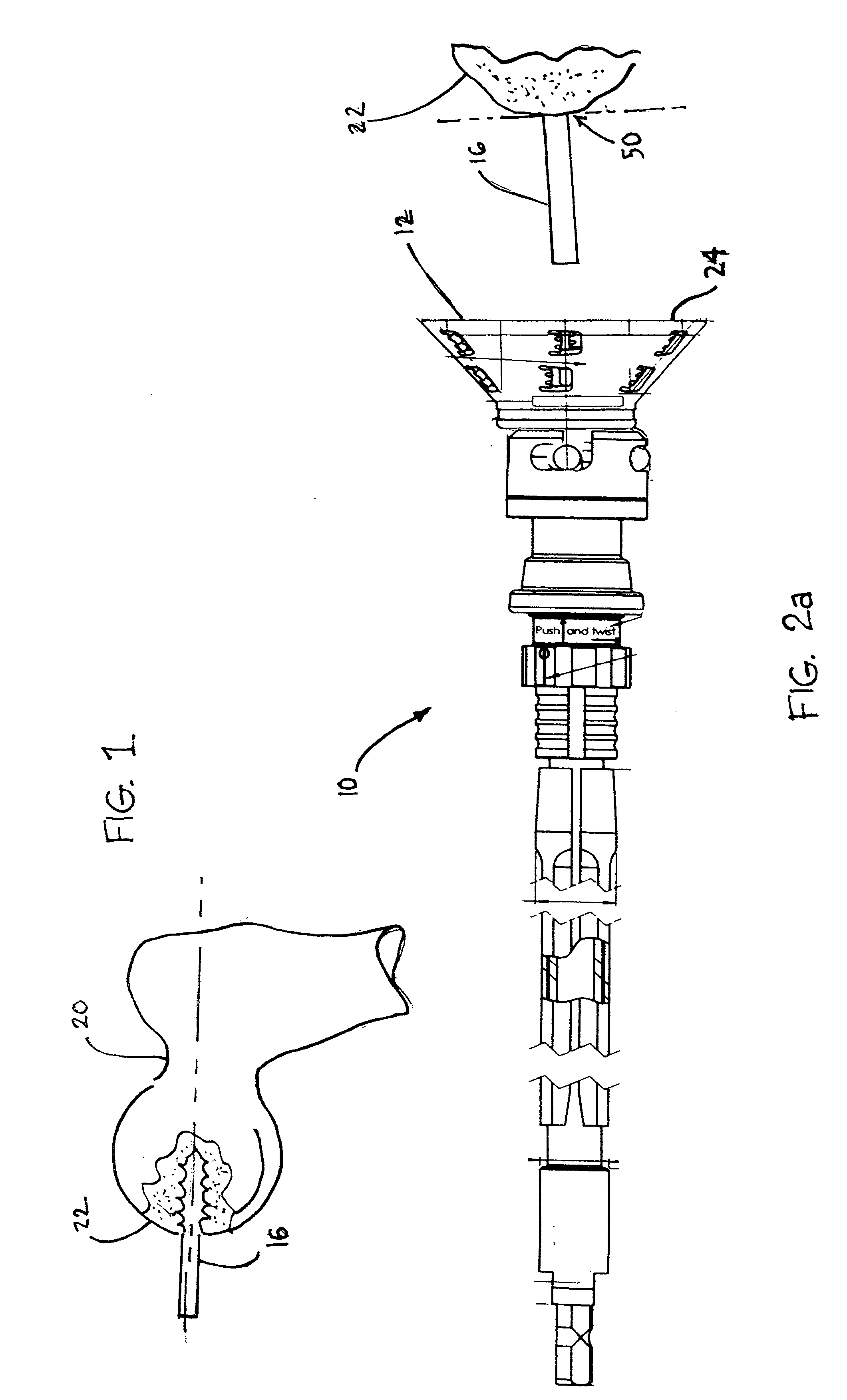
[0025] Referring now to FIG. 1, instead of a total hip replacement, which removes the organic stem 20 of a femoral joint 22 replacing it with an artificial one, processes exist that attempt to preserve the natural joint. One such procedure places a hard, external cap (not shown, but having an eternal spherical form which mates with a socket on its external side and over a resurfaced femoral joint via its internal surfaces). The cap is often made of metal and has precise interface dimensions which must be created on the bone in order for the cap to properly fit over the joint and to properly function in its corresponding prosthetic socket. A drill pin 16 is affixed to the joint 22, axially to the stem 20, in order to prevent damage to the stem, and to guide the cutting tool to precisely shape the joint.

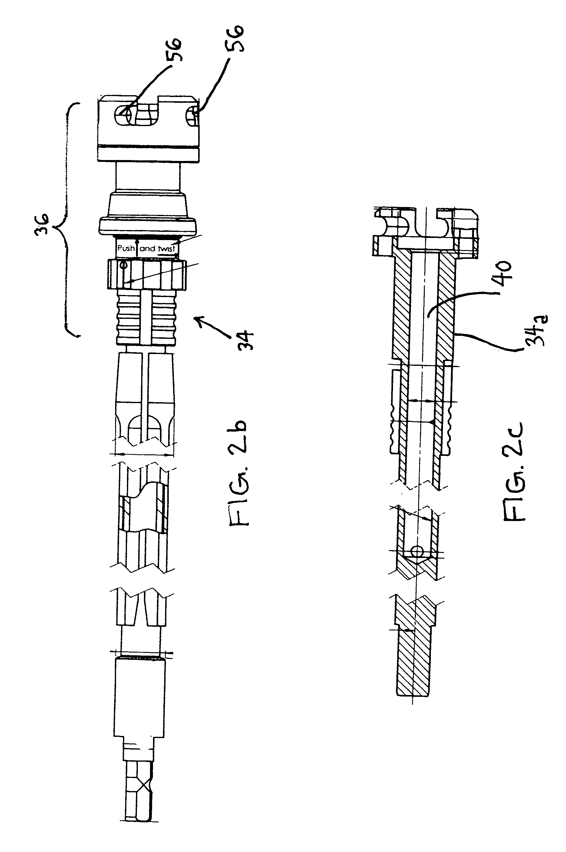
[0026] Referring now to FIGS. 2a-2c and 3a-3c, the system 10 of the invention includes a cannulated reamer 12 and a cannulated reamer handle 34. The cannulated reamer 12 has a centra...


PUM


Abstract

A reamer system is provided which includes a cannulated reamer handle, and a corresponding cannulated reamer, which, when assembled and operated over a drill pin secured in a manner axially aligned with the stem of the femoral joint, enables the accurate and controlled reshaping of the femoral joint. The reamer is made up of a cutting form and a central guide, in which the guide is supported at the center of the cutting form by a bar structure. The bar structure includes portions which connect to and extend radially between the central guide and a peripheral edge of the cutting form. Optionally, the central guide includes a surface offset from a plane of the bar structure to a degree which enables that surface to contact an associated surface referenced to the bone, in order to prevent the cutting form from plunging so far over the bone as to potentially damage the femoral stem. This offset surface is preferably polished to reduce friction during relative rotational movement between this surface and the surface referenced to the bone. The offset surface is an axially perpendicular surface of a boss through which the drill pin is guided.

Description

CROSS REFERENCE TO RELATED APPLICATIONS [0001] This application is a continuation-in-part of U.S. patent application Ser. No. 10 / 441,148 entitled Dual Reamer Holder for Surgical Use which is a continuation-in-part of U.S. patent application Ser. No. 10 / 391,464, entitled Instrument Holder for a Surgical Instrument, filed on Mar. 18, 2003, which is in turn continuation of Ser. No. 09 / 902,369 filed on Jul. 9, 2001, which in turn is a continuation of Ser. No. 602,341 filed Jun. 24, 2000 and now U.S. Pat. No. 6,264,647 issued Jul. 24, 2001, the contents of all of the above applications and patents being incorporated herein by reference thereto.BACKGROUND OF THE INVENTION [0002] The invention relates to a bone shaping system made up of an instrument holder and a surgical instrument for attachment to the holder. The holder includes a shank equipped with a head designed to receive an instrument, and an annular locking component mounted so as to slide about the shank, under the head, equippe...

Claims


Application Information

Patent Timeline
IPC IPC(8): A61B17/16A61B17/17
CPCA61B17/16A61B17/1617A61B2019/4868A61B17/1668A61B17/175A61B17/1666A61B2090/0813
Inventor DESARZENS, YVESLECHOT, ANDRE
Owner VIANT AS&O HLDG LLC
Why Eureka
Try Eureka