Cell permeable structural implant
a technology of permeable implants and cells, applied in the field of biocompatible composites, can solve the problem that the implant lacks porosity enough to permi
- Summary
- Abstract
- Description
- Claims
- Application Information
AI Technical Summary
Benefits of technology
Problems solved by technology
Method used
Image

Examples
example 1
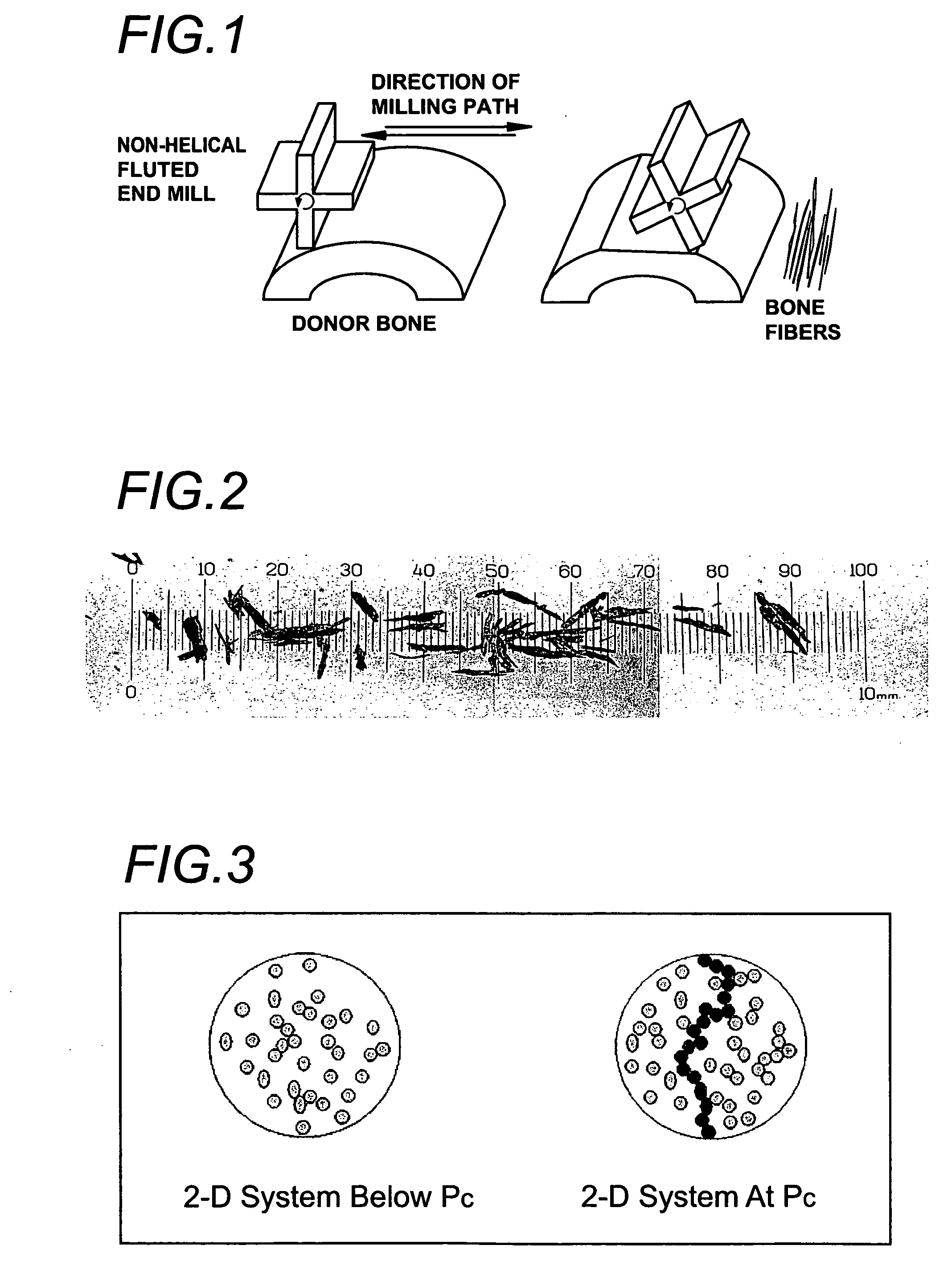
[0117] Compression and fatigue data was generated from samples containing fully mineralized bone fibers and particles. Bone fibers were generated by milling cortical bone with a non-helical four fluted mill and were 300 μm-500 μm wide, with aspect ratios between 3:1 and 10:1. The bone mill was operated at 760 rpm and a pass speed of 0.5 ips. The depth on each pass was 0.02 in. Evenly dimensioned bone particles were generated by grinding and sieving and were 200-500 μm in diameter, with aspect ratios between 1:1 and 2:1. All reported ratios are by weight. The method used to form test samples, apart from bone shape (fiber or particles), was the same. The bone pieces were dried and combined with sufficient polyDTE-carbonate in the assigned proportion (see FIGS. 7 and 8) to make 1-2.5 gram of pre-composite material. The bone / polyDTE-carbonate mixture was charged into a mold and pressurized. The temperature was raised to 110° C. at a rate of 3-4° C. / min., following which the mold was rep...
example 2
[0120] Composite samples were produced from cortical bone particles having relatively even dimensions. Particles from diaphysical bone were ground, lyophilized, and sieved to desired size ranges as discussed below. The particles were combined with one of polyDTE-carbonate, poly L-lactide, poly(DL-co-L-lactide), and polycaprolactone (PCL) in a ratio of 75:25 by weight. The mixtures were molded in a cylindrical press at 13,600 psi and a temperature 15° C. greater than the glass transition temperature of the polymer. Polymeric materials were evaluated for wet compressive strength, both alone and in combination with allograft bone particles (FIG. 9). The lactide materials displayed good wet strength, but when combined with bone (75% bone / 25% polymer, by weight), their strength deteriorated substantially. By contrast, polyDTE-carbonate exhibited significant reinforcement from the bone particles (FIG. 9). The composite withstood 3 million cycles with accelerated cyclic loading at 25 MPa (...
example 3
[0125] Particles of dry cortical rabbit bone were mixed with polymer in a ratio of 60 allograft bone: 40 poly(lactide-co-glycolide) or 75 allograft bone: 25 polyDTE-carbonate by weight, packed into a Carver press, and pressed to 14,300 psi. The heat was then ramped to 110 degrees C. and the implant pressed again up to 14,300 psi. The finished shape of the molded implants was cylindrical, with a diameter of approximately 4.8 mm and length of approximately 15 mm. Implants were sterilized using conventional methods.
[0126] Each composite sample was inserted into a defect created in the lateral femoral condyle of male New Zealand White Rabbits. In each rabbit, a single implant was inserted in both the left and the right femoral condyle. A drill was used to create a hole in the lateral condyle of each femur. The hole was sized such as to allow insertion of the implant, but also provide a tight fit allowing good bone to implant contact. The leading edge of each implant was chamfered to ai...
PUM
| Property | Measurement | Unit |
|---|---|---|
| Length | aaaaa | aaaaa |
| Fraction | aaaaa | aaaaa |
| Fraction | aaaaa | aaaaa |
Abstract
Description
Claims
Application Information