Computer programed method of forming and fabricating parts into an assembly

a computer program and assembly technology, applied in the field of computer programed method of forming and fabricating parts into an assembly, can solve the problems of labor-intensive present practice and human error, and achieve the effect of facilitating positioning

Inactive Publication Date: 2005-11-10
SHOVAN GERALD L
View PDF15 Cites 5 Cited by
  • Summary
  • Abstract
  • Description
  • Claims
  • Application Information

AI Technical Summary

Benefits of technology

[0009] The invention provides a method of fabricating an assembly of at least two metal parts butted together at an interface area by developing a set of three dimensional coordinates corresponding to an assembly of a first part to a second part, developing a programmed set of instructions using the three dimensional coordinates to form the first and seco

Problems solved by technology

Accordingly, the present practice is labor intensive and subject to human error.
However, such indicia are used for assembly and re-assembl

Method used


Image

  • Computer programed method of forming and fabricating parts into an assembly
  • Computer programed method of forming and fabricating parts into an assembly
  • Computer programed method of forming and fabricating parts into an assembly

Examples


Embodiment Construction

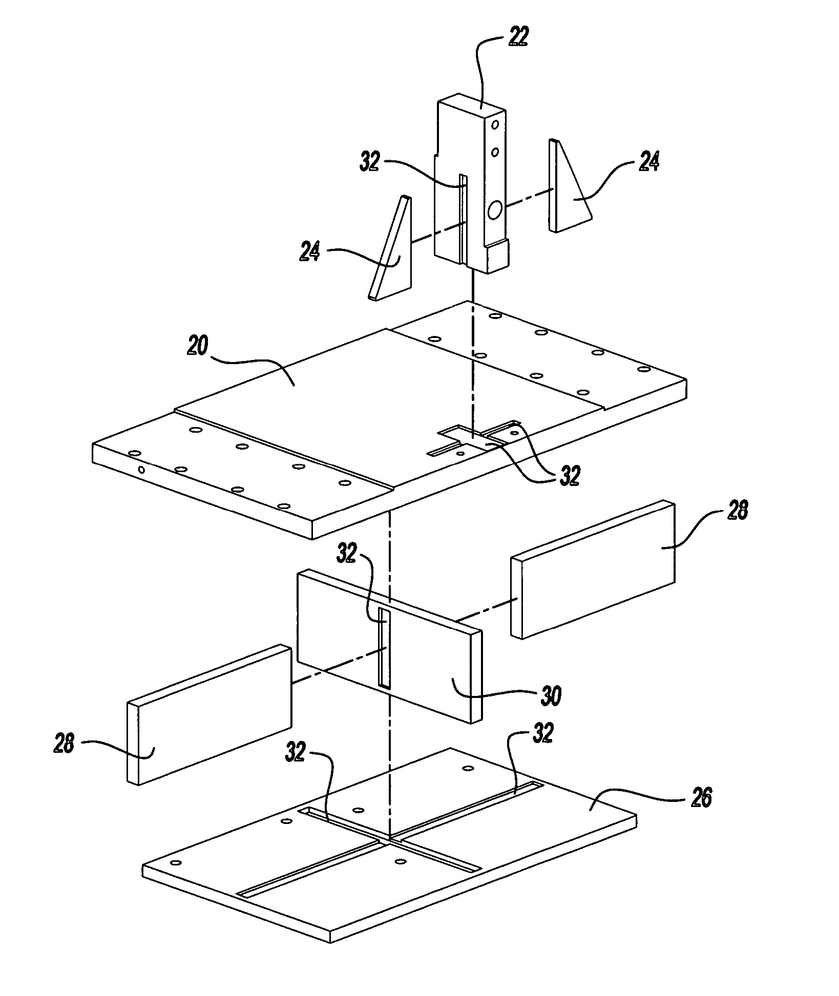
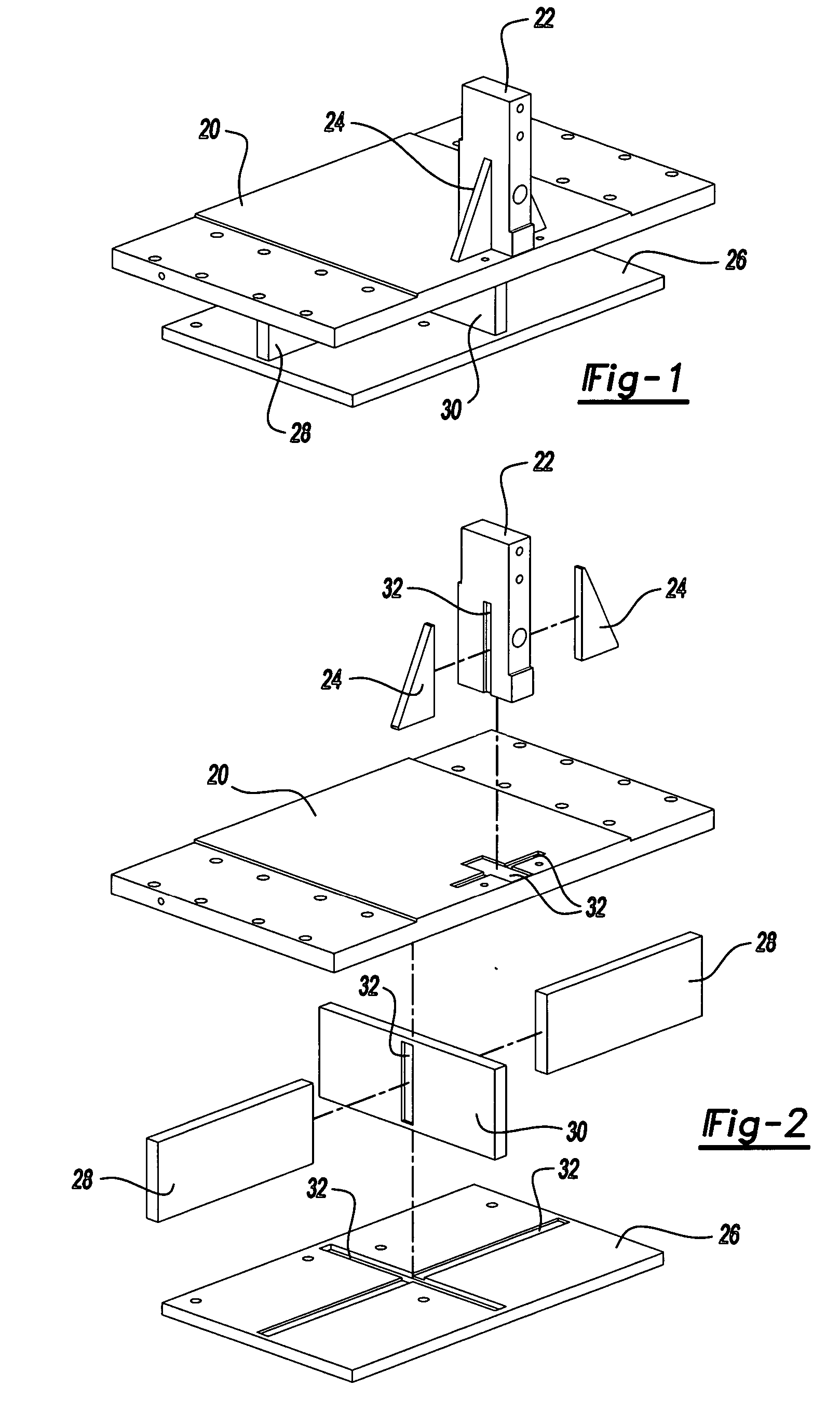
[0018] The subject invention provides a method of fabricating an assembly comprising at least two parts 20, 22, 24, 26, 28 defined by metal plates butted together at a welded interface area 30. An assembly illustrating the invention is shown in FIGS. 1 and 2 and includes a plurality of parts 20, 22, 24, 26, 28. The parts 20, 22, 24, 26, 28 are made of metal and include a platform part 20 with a post part 22 extending upwardly from the top surface of the platform part 20 and triangular reinforcement parts 24 or plates extending between opposite sides of the post part 22 and the top surface of the platform part 20. A base part 26 is held below and in spaced and parallel relationship to the platform part 20 by a pair of first parts 28 extending lengthwise of the base part 26 and a second part 32 extending crosswise of the base part 26 with the first parts 28 abutting the sides of the second part 32. All of the parts 20, 22, 24, 26, 28 are formed from sheets or plates of metal by cuttin...


PUM

PropertyMeasurementUnit
Fractionaaaaaaaaaa
Areaaaaaaaaaaa

Abstract

A method of fabricating an assembly of at least two parts (20, 22, 24, 26, 28) of metal plates butted together at a welded interface area (30) by using a stored CAD program of the three dimensional coordinates of a first part (20, 22, 24, 26, 32) and a second part (32) including the coordinates of an interface area (30) or outline of the first part (20, 22, 24, 26, 32) onto to the second part (32). The parts (20, 22, 24, 26, 28) are cut from stock about the desired peripheries by a cutting tool (34) guided by a sub-file in the computer program and, while the part (20, 22, 24, 26, 32) remains in the cutting machine (36), the program guides the cutting tool (34) to cut out a recessed area (30) in the second part (32) for receiving the first part (20, 22, 24, 26, 32) into the recessed area (30) of the second part (32). The first part (20, 22, 24, 26, 32) is welded to the second part (32) about the recessed area (30) to create a permanent interface area (30).

Description

CROSS REFERENCE TO RELATED APPLICATION [0001] This application claims the benefit of provisional application Ser. No. 60 / 566,038 filed Apr. 28, 2004.BACKGROUND OF THE INVENTION [0002] 1. Field of the Invention [0003] The subject invention relates to a method of fabricating an assembly of a plurality of parts of metal plates butted together at a welded interface area. [0004] 2. Description of the Prior Art [0005] In order to fabricate such parts it has been customary to prepare a detailed drawing of each part with a relatively complete array of interrelated dimensions on the drawing. For example, such dimensions would include lengths and widths with dimensions relative thereto for other shapes in each part plus angles, diameters and axes. [0006] In addition, a fabricator must refer to the drawings to position the parts relative to one another for securing or welding the parts together. This is being done by measuring and manually scribing the parts at the intended interface of the pa...

Claims


Application Information

Patent Timeline
IPC IPC(8): G05B19/4099G06F19/00
CPCG05B19/4099G05B2219/35027Y10T29/49G05B2219/35219G05B2219/45055G05B2219/35196Y02P90/02
Inventor SHOVAN, GERALD L.KOSTOS, STEVEN LEE
Owner SHOVAN GERALD L
Why Eureka
Try Eureka