

Roofing shingles provided with release coating
a technology of release coating and roof shingles, which is applied in the direction of roof covering, roofing, construction, etc., can solve the problems of shingles at the bottom of a stack being more prone to sticking than those at the top, shingles to stick together, distortion and localized sticking of shingles, etc., to achieve the effect of reducing the cost of processing, reducing the cost of components, and reducing the cost of shingles to the bottom of a stack
Inactive Publication Date: 2005-11-17
BUILDING MATERIALS INVESTMENT
View PDF3 Cites 10 Cited by
- Summary
- Abstract
- Description
- Claims
- Application Information
AI Technical Summary
Benefits of technology
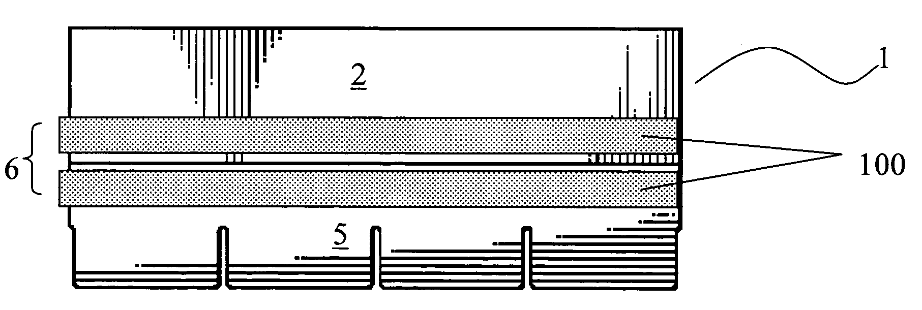
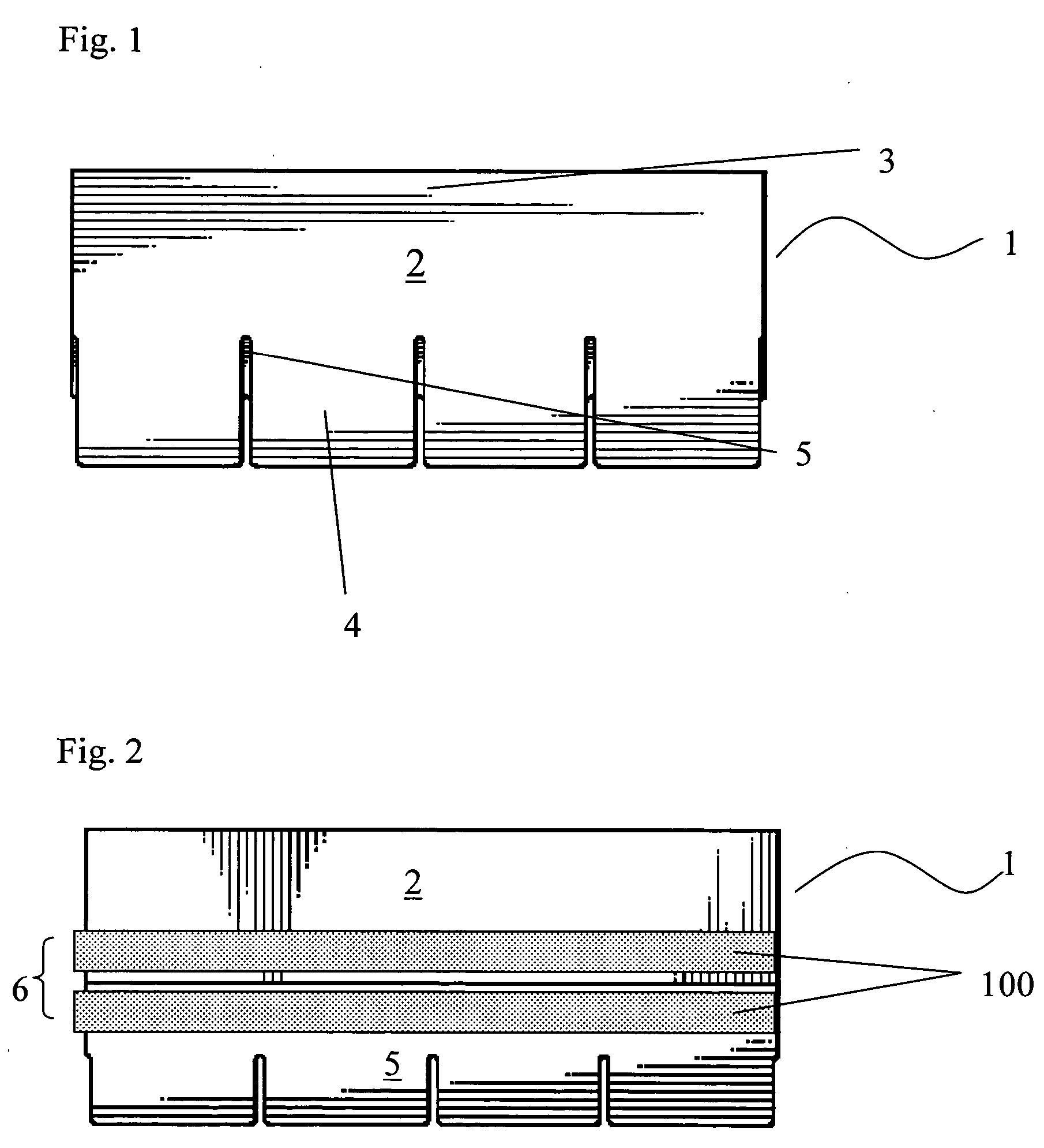
[0011] A new roofing shingle has now been developed which overcomes the problem of sticking together of roofing shingles, when stacked in a plurality of roofing shingles and disposed on pallets, during transit and storage. This new shingle design does not adversely affect roofing shingle performance in protecting roofs and represents a minimal additional expense in terms of additional processing complexity and component cost.
Problems solved by technology
A problem associated with both laminated and strip roofing shingles lies in shipment and storage of these shingles.
Independent of the bundling method, the high pressure caused by stacking of these heavy roofing shingles, causes the shingles to stick together.
This pressure point results in distortion and localized sticking of the shingles.
Thus, shingles at the bottom of a stack are more prone to sticking than those at the top where the pressure is lower.
The combination of high temperature and long storage times results in very damaging sticking.
This method has been successful, albeit not 100% effective.
Not only is this method not totally effective but, in addition, application of release tape adds significant material and labor expense.
Method used
View moreImage
Smart ImageViewing Examples

Examples
example 1
[0092] Comparative Example 1 was identically reproduced but for the application on the pressure point portion of the bottom side of the shingles of a coating of Nytal® 100 talc. The dilution ratio of the release coating was five parts water to one part Nytal.
[0093] The average force required to separate the 11 roofing shingles was 7.69 lbs. with a standard deviation of 3.74 lbs.
examples 2-6
[0094] Example 1 was reproduced except that the coating of that example was replaced with Graphite 100® synthetic graphite in Example 2; Microlite® vemiculite in Example 3; Desulco® graphite in Example 4; Vantal® 6H magnesium silicate in Example 5; and Nytal®400 talc in Example 6.
[0095] Each example involved 11 roofing shingle separations.
Login to View More PUM
 Abstract
A roofing shingle and a method of manufacturing a roofing shingle wherein the bottom surface of said shingle is provided with a release coating of a continuous film of particles having poor interlaminar strength due to the particles having good to perfect basal cleavage. The release coating significantly eases separation of roofing shingles that stick together when stacked during storage and transit in warm environments.
Description
BACKGROUND OF THE INVENTION [0001] 1. Field of the Invention [0002] The present invention is directed to roofing shingles provided with a release coating. More specifically, the present invention focuses upon laminated roofing shingles whose bottom surface is coated with a continuous film of release material characterized by poor interlaminar strength. [0003] 2. Background of the Prior Art [0004] Roofing shingles are often divided into two main groups: strip shingles and dimensional or laminated shingles. The most common type of roofing shingles are laminated. These laminated shingles, often referred to as “architectural shingles,” include a top layer, which those skilled in the art speak of as the “anterior layer” and a bottom layer, referred to as the “posterior layer.” The back surface of the anterior layer is bonded to the front surface of the posterior layer. The posterior layer is bonded so that it mates with the lower butt portion of the anterior layer and further overlaps th...
Claims
Login to View More Application Information
Patent Timeline
 IPC IPC(8): E04D1/26E04D1/34
CPCE04D2001/005E04D1/26
InventorKERKAR, AWDHOOT VASANTRODRIGUES, TOMMYSIELING, FREDERICK W.
OwnerBUILDING MATERIALS INVESTMENT