
Method and arrangement for detecting parameters in displacement or angle sensors

a technology of displacement or angle sensor and detecting parameters, which is applied in the direction of measuring devices, instruments, devices using electric/magnetic means, etc., can solve the problems of static detection and if needed correction of production process, for instance, inability to detect static or no-go test methods, etc., and achieve the effect of minimal additional costs

Inactive Publication Date: 2006-06-15
ROBERT BOSCH GMBH
View PDF5 Cites 6 Cited by
  • Summary
  • Abstract
  • Description
  • Claims
  • Application Information

AI Technical Summary

Benefits of technology

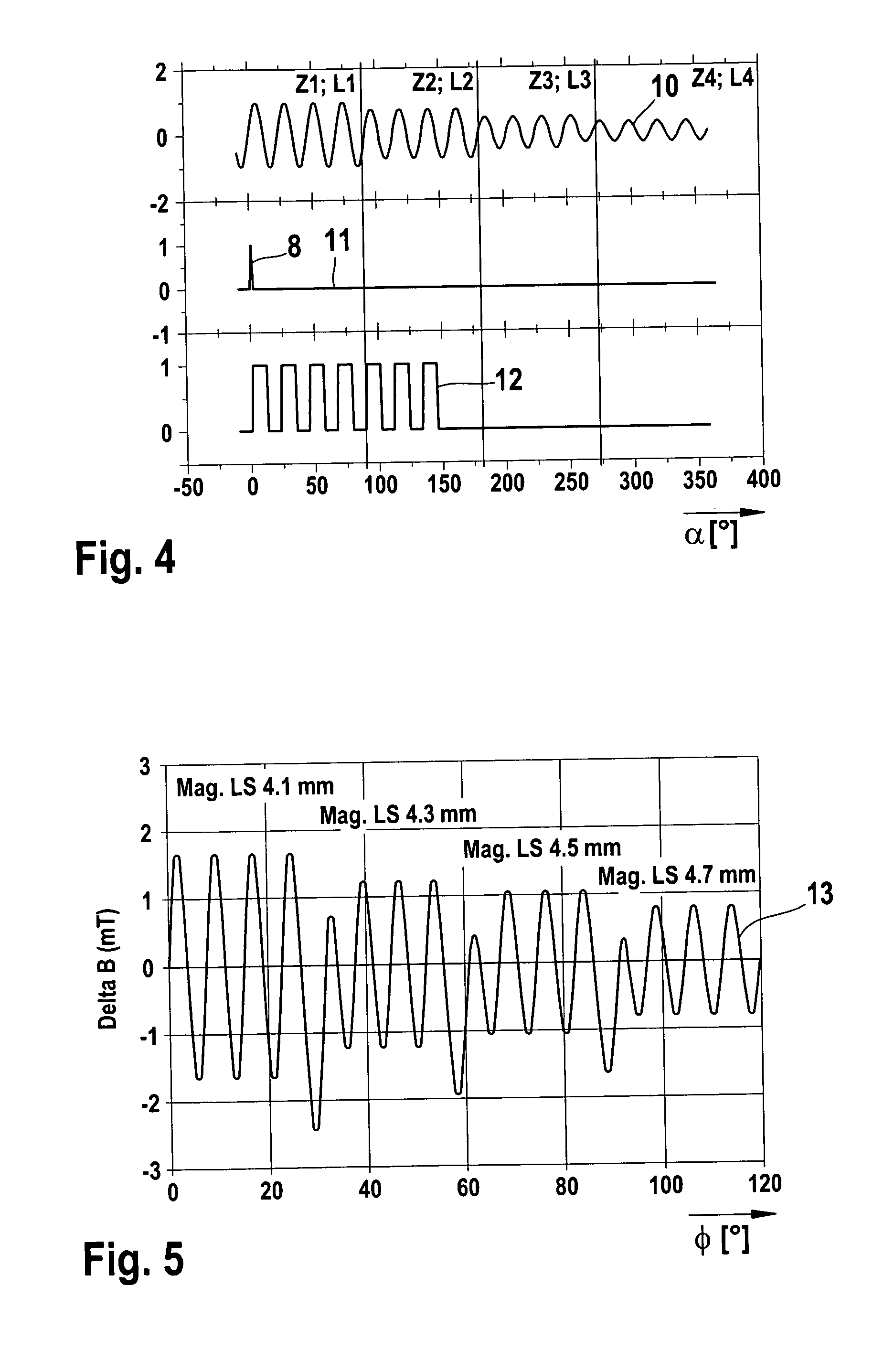
[0010] With the invention, a test method can advantageously be implemented which makes a quantitative determination of the attainable air gap possible for each sensor manufactured. The test procedure is not lengthened in duration by this. In this way, it is thus possible at minimal additional expense to detect the attainable air gap statistically during production and use it for both controlling and optimizing the production processes.

Problems solved by technology

The go / no-go test method, however, is in no way appropriate for the importance of the air gap as a parameter in production, since with it, static detection and if needed correction of the production process, for instance, is not possible.

Method used


Image

  • Method and arrangement for detecting parameters in displacement or angle sensors
  • Method and arrangement for detecting parameters in displacement or angle sensors
  • Method and arrangement for detecting parameters in displacement or angle sensors

Examples


Embodiment Construction

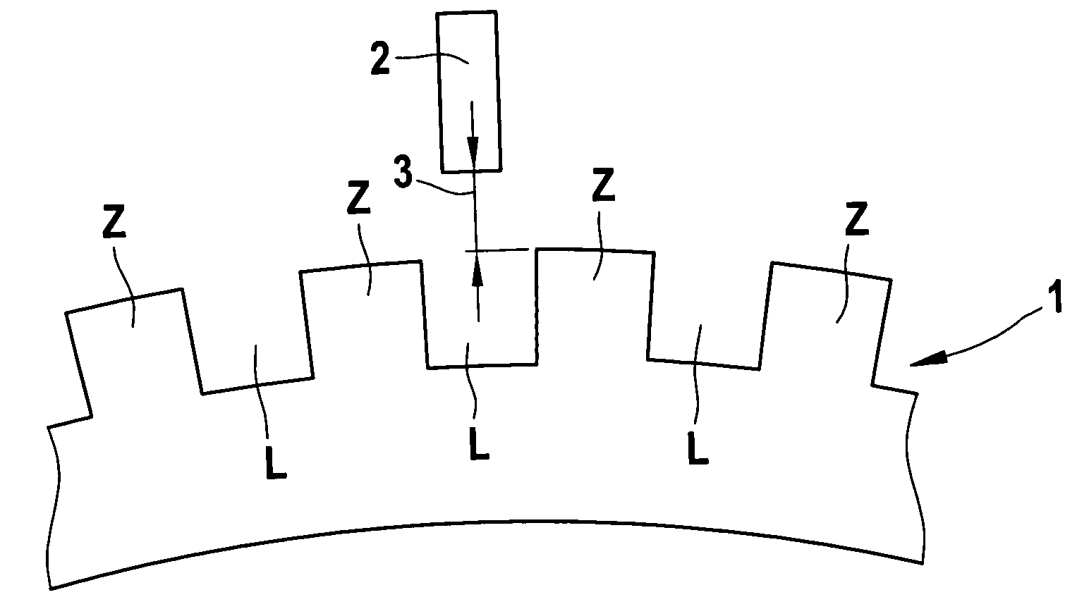
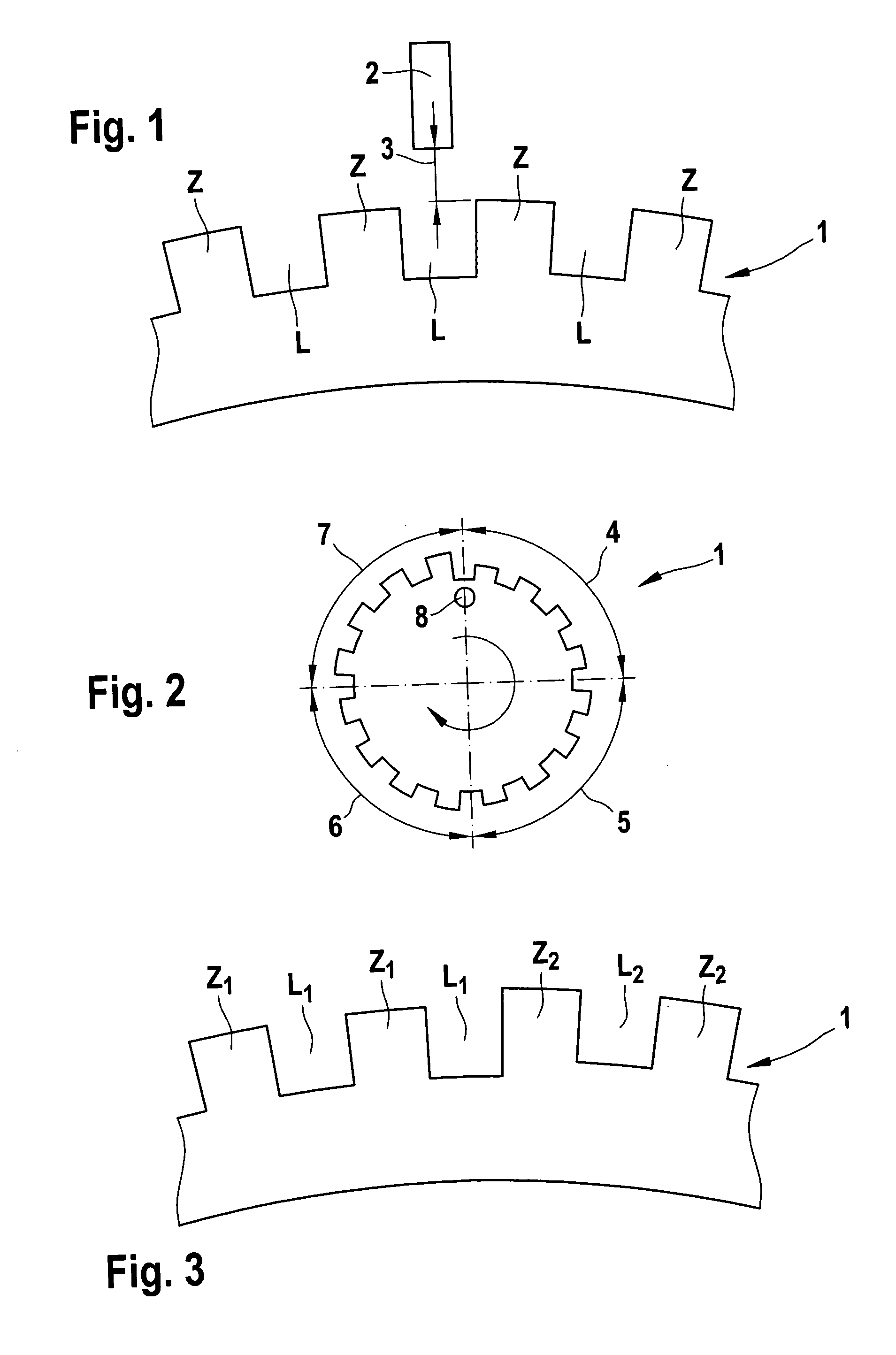
[0019] In FIG. 1, in a schematic view, part of a transducer wheel 1 is shown, which is provided on its circumference with a tooth-gap contour Z, L. There is also a magnetic-field- sensitive sensor 2, as an rpm sensor, which is diametrically opposite the tooth-gap contour Z, L across an air gap 3. As the transducer wheel 1 below the sensor 2 rotates past it, the switching edges that are tripped by the field variation on the part of the tooth-gap contour Z, L, can be evaluated, if the size of the air gap 3 permits the generation of a sensor output signal.

[0020] In a test apparatus, a qualitative effect of the air gap 3 is now to be performed by measurement with a transducer wheel 1 of FIG. 2 and FIG. 3; this measurement can be achieved with an arbitrary sensor configuration. To that end, the transducer wheel 1 of FIG. 2 has a variation in the tooth-gap contour in terms of the height of both the teeth Z and the gaps L. In this transducer wheel 1, there are four periods 4, 5, 6 and 7, ...


PUM


Abstract

In method and an arrangement for detecting parameters in displacement or angle sensors, in a test procedure sensor signals in a stationary sensor are evaluated, which signals are generated by scanning a plurality of code elements located side by side, perpendicular to a direction of motion, on a transducer element as a moving component; and the test procedure is performed with a transducer element that has a predetermined variation of geometrical variables of the code elements.

Description

BACKGROUND OF THE INVENTION [0001] The present invention relates to a method and an arrangement for detecting parameters, in particular the air gap in magnetic sensor arrangements, in displacement or angle sensors. [0002] It is known per se that for detecting rotary speeds or rotational angle changes, for instance in motor vehicles, rpm sensors are used for measuring the rotary speed of wheels, for electronic stability control systems, or in engine control. These sensors can evaluate an angular position, for instance, on the basis of pulses generated optically, magnetically, or otherwise, by the rotation and detected by suitable means. [0003] Particularly in magnetic measuring methods, knowledge of the maximum allowable air gap between the transducer element and the sensor is very important, if a reliable measurement method is to be obtained. The maximum allowable air gap, in the applications described above, is the air gap at which it is assured that under all operating conditions,...

Claims


Application Information

Patent Timeline
Patent Type & Authority Applications(United States)
IPC IPC(8): G01P3/44G01B7/30G01B21/22
CPCG01D5/2451G01D5/2457
Inventor RETTIG, RASMUSZWIENER, GUENTERSCHMIDT-GRETHE, KARSTENBAUER, CHRISTIAN
Owner ROBERT BOSCH GMBH
Learn More