
Condensation removal for use with a draft inducer

a technology of inducer and condensation, which is applied in the direction of air heaters, machines/engines, lighting and heating apparatus, etc., can solve the problems of fuel exhaust, and achieve the effect of reducing the temperature of the mixtur

Inactive Publication Date: 2005-11-17
COMAIR ROTRON
View PDF13 Cites 0 Cited by
  • Summary
  • Abstract
  • Description
  • Claims
  • Application Information

AI Technical Summary

Benefits of technology

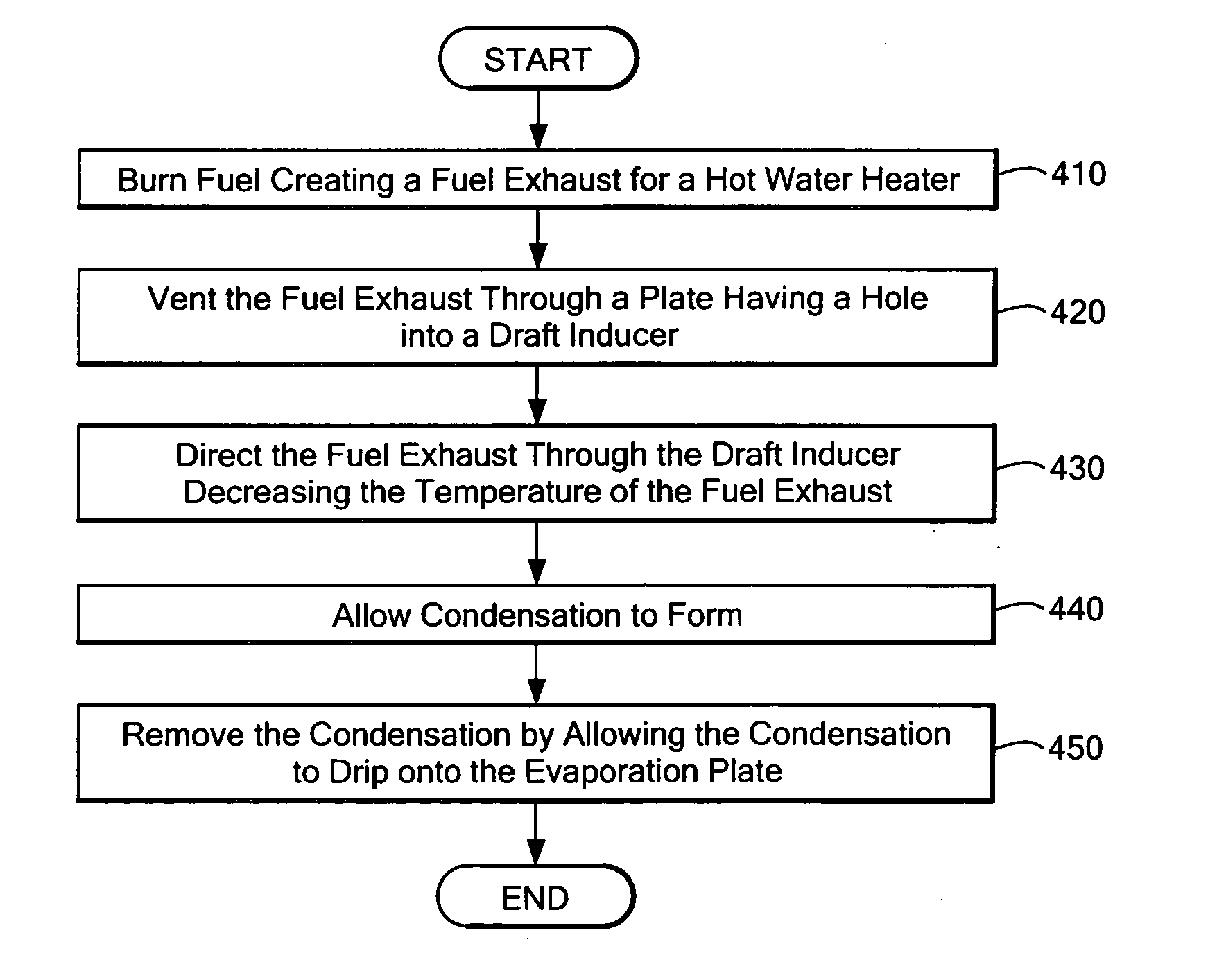
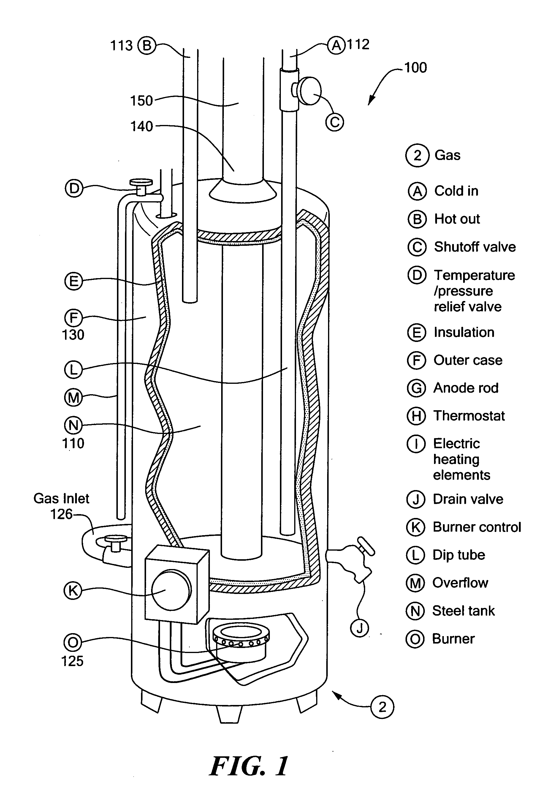
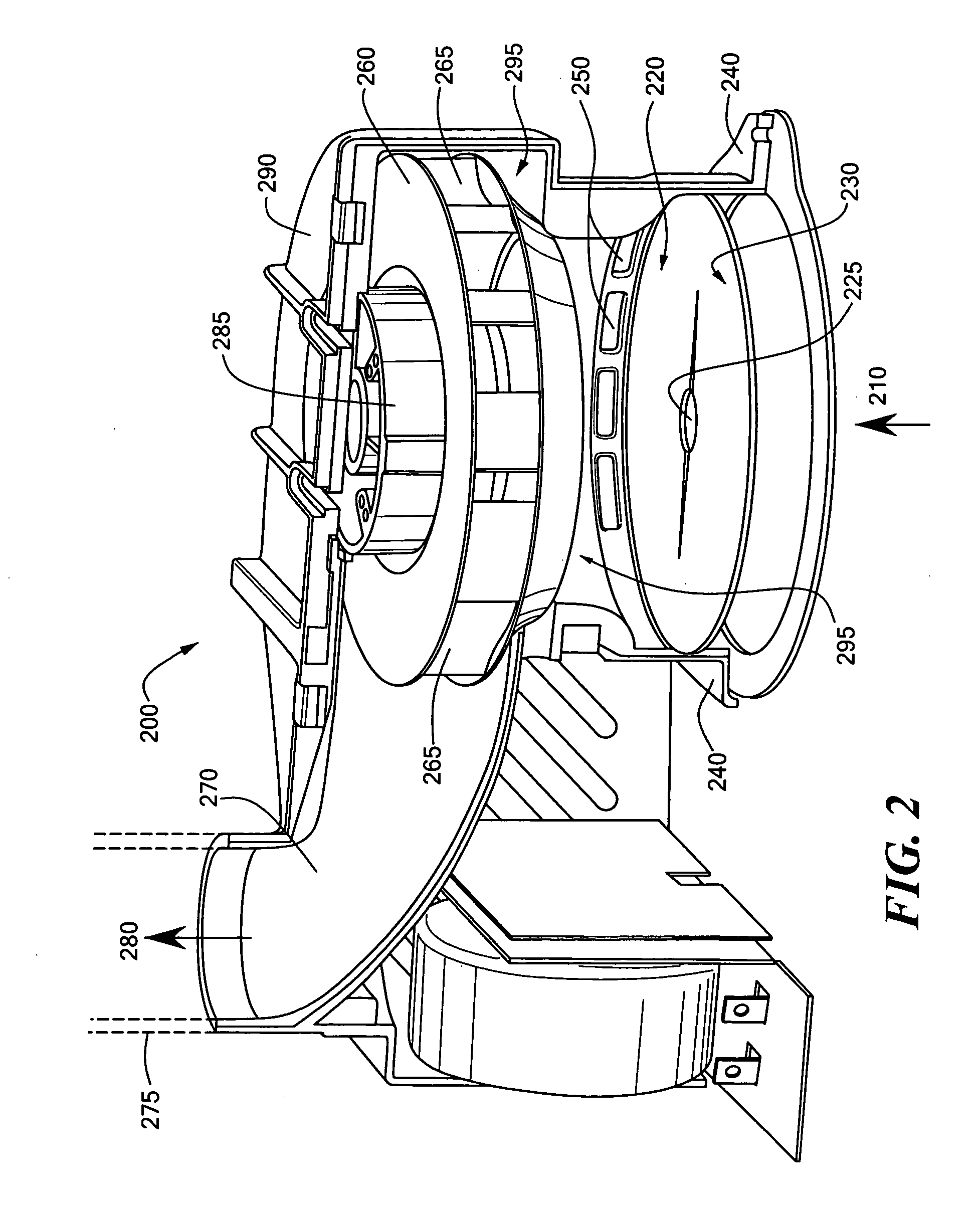
[0005] In a first embodiment of the invention there is provided a condensation removal apparatus. The condensation removal apparatus is used with a hot water heater wherein the hot water heater produces an exhaust. When a hot water heater heats hot water, a fuel is ignited and burned. This process causes the resulting fuel exhaust. The fuel exhaust is vented from the hot water heater through an outlet to a draft inducer. The draft inducer has an inlet for receiving the fuel exhaust. The inlet is formed by a hole in a thermally conductive plate. The hole may take the form of any shape. As the fuel exhaust passes through the hole, the plate is heated. The plate's temperature is raised by the exhaust such that the plate can turn condensation into a gaseous form. In one embodiment, the thermally conductive plate is convex in shape. The convex shape prevents any condensation that reaches the thermally conductive plate from reaching the hot water heater. In one embodiment, the hole is at the center of the plate. Any condensation that reaches the plate is turned into a gaseous state and is forced back out through the draft inducer.
[0006] The thermally conductive plate is sized to fit within the inlet of the draft inducer. The draft inducer includes a mixing chamber. The thermally conductive plate sits between the outlet of the hot water heater and the mixing chamber. The mixing chamber of the draft inducer includes one or more openings that allow ambient air to flow into the mixing chamber. An impeller situated above the mixing chamber draws ambient air into the mixing chamber, causing a vortex and mixing the fuel exhaust with the ambient air. The fuel exhaust and ambient air mixture is drawn through the impeller and redirected approximately ninety degrees. In one embodiment, the impeller is a backwards curved impeller. The backwards curved impeller is powered by a DC motor which resides within the impeller housing. As the ambient air mixes with the fuel exhaust the temperature of the mixture is reduced as compared to the fuel exhaust. The mixture is directed to an outlet of the draft inducer and through piping into another environment. As the mixture cools, condensation forms within the piping. The condensation drips back down through the draft inducer. The condensation is then directed onto the thermally conductive plate. Since the thermally conductive plate maintains a high temperature, the condensation is turned from a liquid form into a gaseous form and is directed back through the draft inducer to the outlet.

Problems solved by technology

This process causes the resulting fuel exhaust.

Method used


Image

  • Condensation removal for use with a draft inducer
  • Condensation removal for use with a draft inducer
  • Condensation removal for use with a draft inducer

Examples


Embodiment Construction

[0012] Definitions. As used in this description and the accompanying claims, the following terms shall have the meanings indicated, unless the context otherwise requires: In the following disclosure the term “exhaust” shall refer to both the fuel exhaust that comes directly from the hot water heater, as well as, the ambient air and fuel exhaust mixture unless the context requires a different meaning.

[0013]FIG. 1 is schematic diagram of a hot water heater. A hot water heater 100 includes a tank 110 having an inlet 112 and an outlet 113. The inlet 112 allows unheated water to flow into the tank 110. The outlet 113 allows heated water to flow out of the tank 110. The hot water heater 100 also includes a fuel source 120 and an ignition device 125 for igniting and burning the fuel source. The water tank 110 along with the ignition device 125 and the fuel inlet 126 for the fuel source are encased in a housing 130. The heat from the ignited fuel source 120 heats the water tank 110 which t...


PUM


Abstract

A condensation removal apparatus is disclosed. The condensation removal apparatus is used with a hot water heater wherein the hot water heater produces a fuel exhaust. The fuel exhaust from the hot water heater is provided to a draft inducer through an inlet which includes a thermally conductive plate having a hole through which the fuel exhaust flows. The draft inducer mixes ambient air with the fuel exhaust and reduces the temperature of the mixture as compared to the fuel exhaust. The mixture is directed to an outlet of the draft inducer and through piping into another environment. As the mixture cools, condensation forms within the piping. The condensation drips back down through the draft inducer. The condensation is then directed onto the thermally conductive plate. Since the thermally conductive plate maintains a high temperature, the condensation is turned from a liquid form into a gaseous form and is directed back through the draft inducer to the outlet.

Description

CROSS REFERENCE TO RELATED APPLICATIONS [0001] The Following Application incorporates by reference in its entirety the co-pending U.S. patent application entitled Draft Inducer having a Backwards Curved Impeller having attorney docket number 917 / 194 and filed concurrently herewith. TECHNICAL FIELD AND BACKGROUND ART [0002] The present invention relates to condensation removal and specifically condensation removal in draft inducers. [0003] Hot water heaters heat water in a tank by burning a fuel source, heating the tank, which transfers the thermal energy to the water, and thereby increases the water's temperature. As the fuel burns, the fuel produces a hot exhaust which is vented away from the hot water heater. In certain hot water heaters draft inducers are used to cool the exhaust. As the exhaust cools, a small amount of the exhaust condenses within either the draft inducer or the ventilation piping leading from the hot water heater. This condensation can then flow back into the d...

Claims


Application Information

Patent Timeline
Patent Type & Authority Applications(United States)
IPC IPC(8): F23L17/00F24H8/00
CPCF23L17/005Y02B30/104F24H8/003Y02B30/00
Inventor BROWN, FRED A.
Owner COMAIR ROTRON
Learn More