Air conditioning system

a technology for air conditioning and systems, applied in the field of air conditioning systems, can solve the problems of air conditioning systems that allow removing, and achieve the effects of low manufacturing cost, convenient and efficient manufacturing and marketing, and durable and reliable construction

Inactive Publication Date: 2005-11-17
MORATALLA JOSE
View PDF4 Cites 56 Cited by
  • Summary
  • Abstract
  • Description
  • Claims
  • Application Information

AI Technical Summary

Benefits of technology

[0018] It is another object of the present invention to provide a new and improved air conditioning system which may be easily and efficiently manufactured and marketed.
[0019] It is a further object of the present invention to provide a new and improved air conditioning system which is of durable and reliable constructions.
[0020] An even further obje

Problems solved by technology

While these devices fulfill their respective, particular objectives and requirements, the aforementioned patents do not describe a air conditioning system that allows remov

Method used


Image

  • Air conditioning system
  • Air conditioning system
  • Air conditioning system

Examples


Embodiment Construction

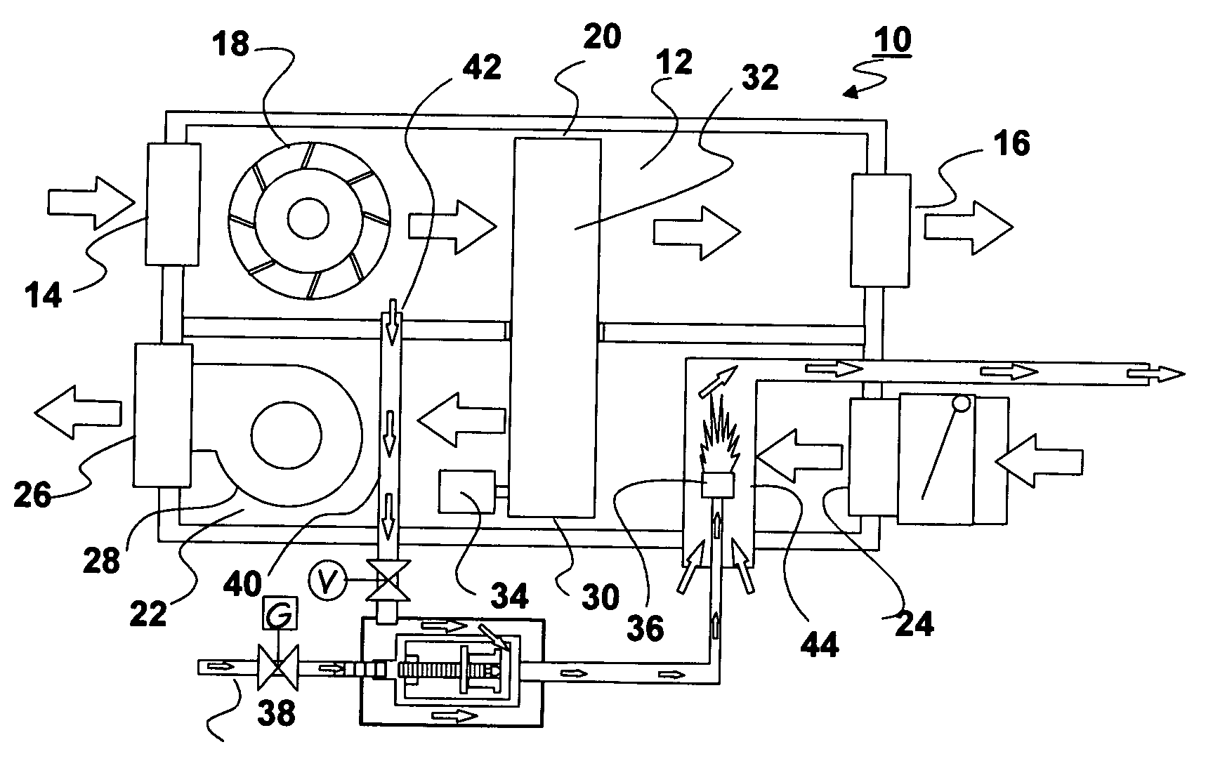
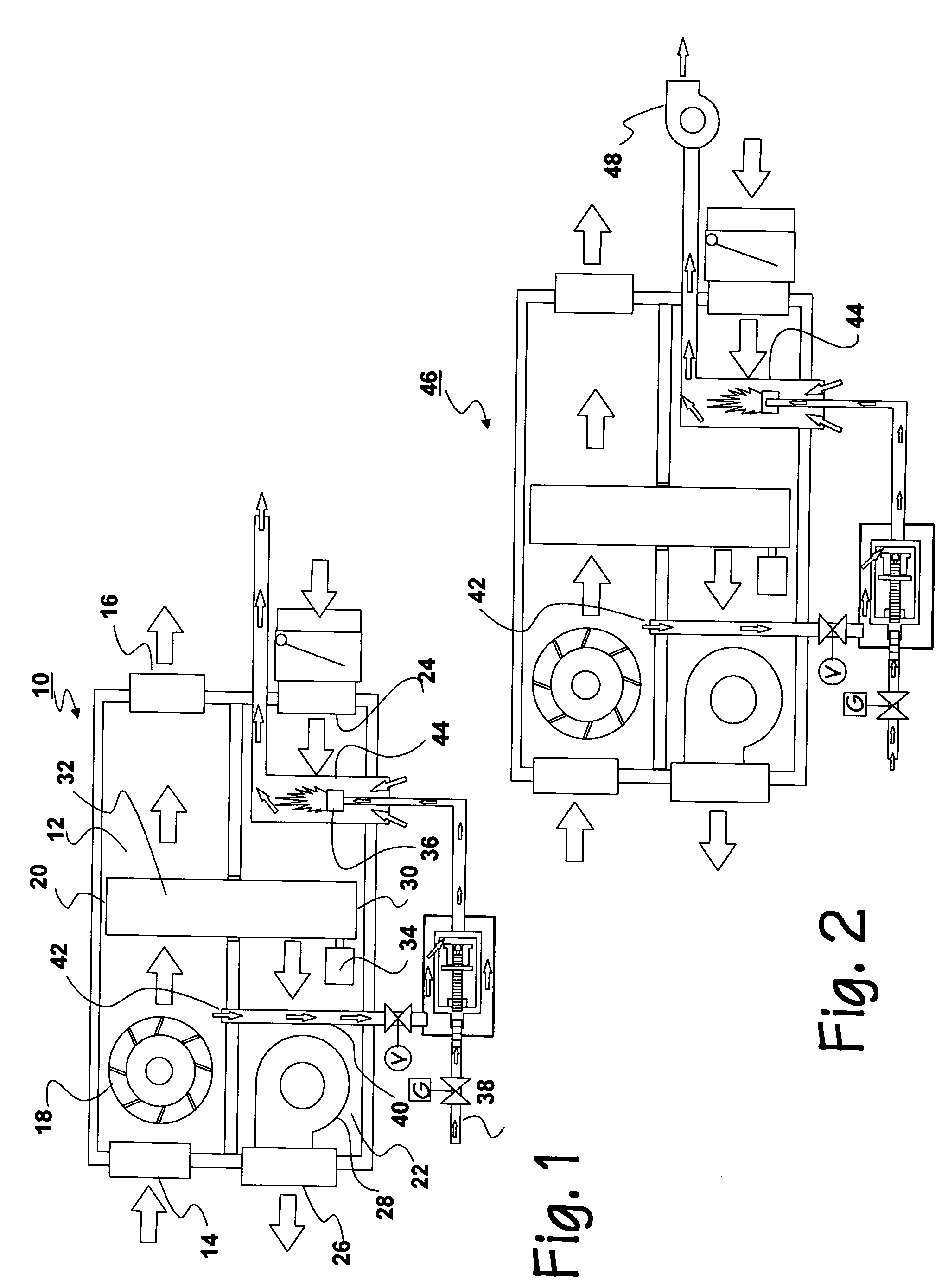
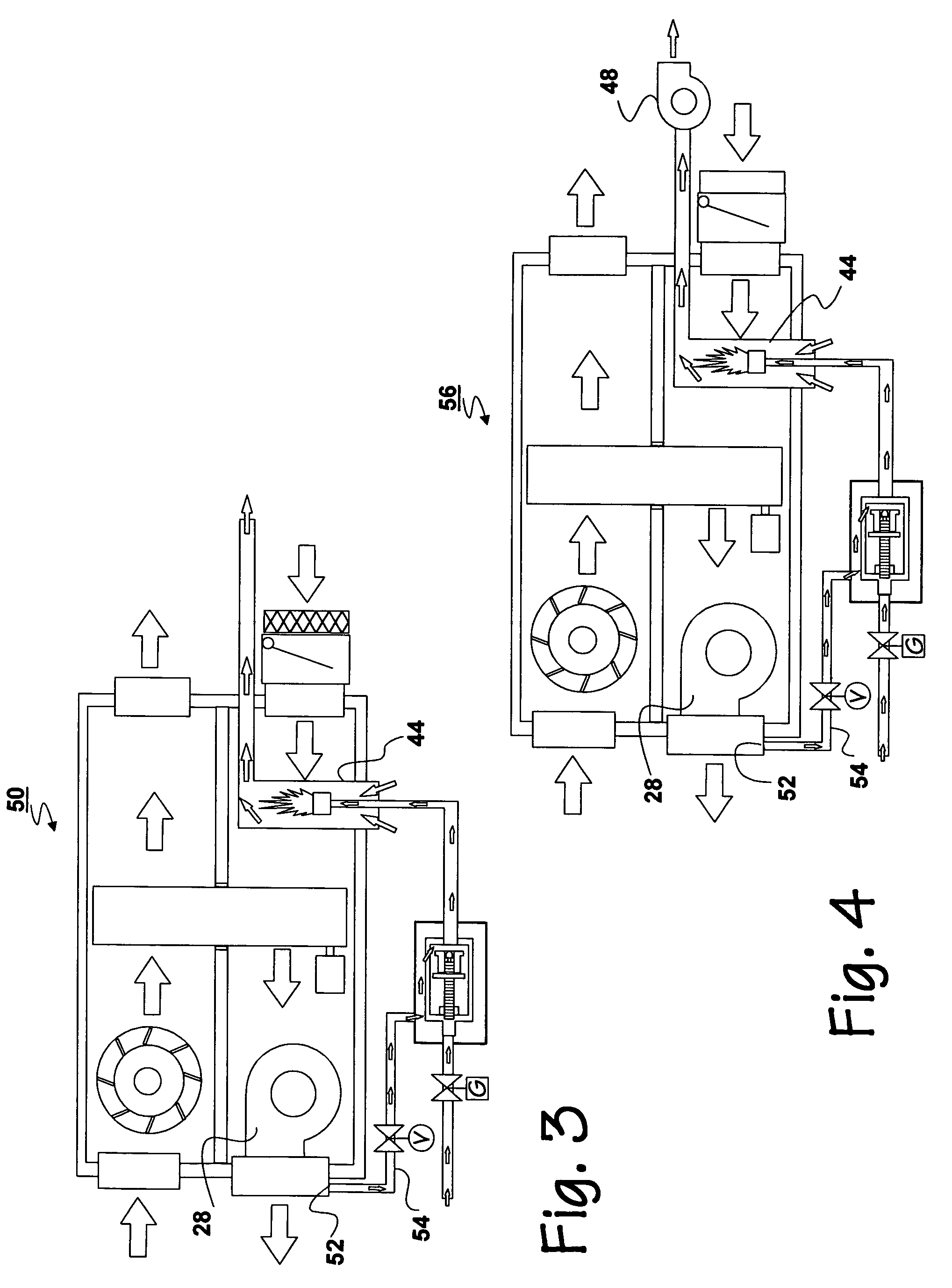
[0056] With reference now to the drawings, and in particular to FIG. 1 thereof, the preferred embodiment of the new and improved air conditioning system embodying the principles and concepts of the present invention and generally designated by the reference numeral 10 will be described.

[0057] The present invention, the air conditioning system 10 is comprised of a plurality of components. Such components in their broadest context include first and a second air paths, a desiccant wheel, a gas heater and also gas and air feed lines. Such components are individually configured and correlated with respect to each other so as to attain the desired objective.

[0058] Illustrated in FIG. 1, and pertinent to the embodiments of FIGS. 1 through 8, is an air conditioning system 10 for controlling humidity in an efficient and economical manner. The system includes a first air path 12 having an input end 14 and an output end 16 and with a first fan 18 adapted to move air in a first direction towa...


PUM


Abstract

A first air path with a first fan is adapted to move air in a first direction and a moisture absorbing zone. A second air path with a second fan is adapted to move air in a second direction and a moisture desorbing zone. A rotatable desiccant wheel is located partially in the moisture absorbing zone and partially in the moisture desorbing zone. A heater in the second air path is adapted to desorb moisture from the desiccant wheel. A gas feed line and an air feed line supply the heater. The air feed line has an inlet adjacent to one of the fans.

Description

RELATED APPLICATIONS [0001] The present application is a continuation-in-part of U.S. patent application Ser. No. 10 / 517,967 filed Dec. 14, 2004 which is based upon International Application Number PCT / US03 / 03729 filed Feb. 6, 2003 which, in turn, is based upon U.S. Provisional Application 60 / 354,682 filed Feb. 6, 2002.BACKGROUND OF THE INVENTION [0002] 1. Field of the Invention [0003] The present invention relates to air conditioning systems and, more particularly to controlling the temperature and humidity independently in an efficient and economical manner. [0004] It has always been a desire to manipulate air conditions for comfort and to meet specific conditions required for certain facilities. Typically, these prior art systems have directly heated or cooled the outside air and / or air return from a structure and then exhausted the air into the structure. One of the effects of cooling an air stream is the resulting change in the moisture content of the air. It is well recognized...

Claims


Application Information

Patent Timeline
IPC IPC(8): B01D53/26F24F3/14
CPCB01D53/26F24F3/1411F24F3/1423F24F2003/144F24F2203/1008F24F2203/1084F24F2203/1024F24F2203/1032F24F2203/1064F24F2203/1068F24F2203/1016
Inventor MORATALLA, JOSE
Owner MORATALLA JOSE
Why Eureka
Try Eureka