Drum assembly for washing machine

a drum and washing machine technology, applied in the field of washing machines, can solve the problems of complicated assembly process and long time for an assembler, and achieve the effects of improving the structure of the drum assembly of the washing machine, fixing the lifter to the drum quickly and easily, and improving the structure of the drum assembly

Inactive Publication Date: 2005-11-17
LG ELECTRONICS INC
View PDF4 Cites 72 Cited by
  • Summary
  • Abstract
  • Description
  • Claims
  • Application Information

AI Technical Summary

Benefits of technology

[0010] An object of the present invention is to improve a structure of a drum assembly of the washing machine so that an assembler can fix lifters to a drum quickly and easily.
[0011] Another object of the present invention is to improve the structure of the drum assembly of the washing machine so that lifters are stably secured to the drum.
[0017] The slot of the drum may further comprise at least one rounded portion provided between the wide portion and the narrow portion, and smoothly guiding the hook put into the wide portion into the narrow portion. Wherein, the rounded portion is provided on both sides of the narrow portion, or is provided on one side of the narrow portion.
[0019] The drum may further comprise a projection extended from the drum and supporting the lifter so as to prevent the lifter from sliding backward after the lifter is secured to the drum. The lifter may be configured to go over the projection when the lifter slides on the inner surface of the drum so as to be secured to the drum. Wherein, the projection comprises a slope provided on an upper surface of the projection so that the lifter smoothly goes over the projection along on the slope when the lifter slides so as to be coupled to the drum.
[0021] The lifter may further comprise a protrusion extended from the lifter, wherein the protrusion is engaged with the projection so as to prevent the lifter from sliding backward after the lifter is secured to the drum.
[0023] The drum may further comprise at least one projection extended from the drum between the pair of slots, wherein the projection supports the lifter so as to prevent the lifter from sliding backward after the lifter is secured to the drum.

Problems solved by technology

Thus, there are disadvantages in the above mentioned coupling structure of the drum and the lifter that it takes long time for an assembler to fix the lifters to the drum and that the assembling process for producing the washing machine become complicated.

Method used


Image

  • Drum assembly for washing machine
  • Drum assembly for washing machine
  • Drum assembly for washing machine

Examples


Embodiment Construction

[0030] Reference will now be made in detail to the preferred embodiments of the present invention, examples of which are illustrated in the accompanying drawings. Wherever possible, the same reference numbers will be used throughout the drawings to refer to the same or like parts.

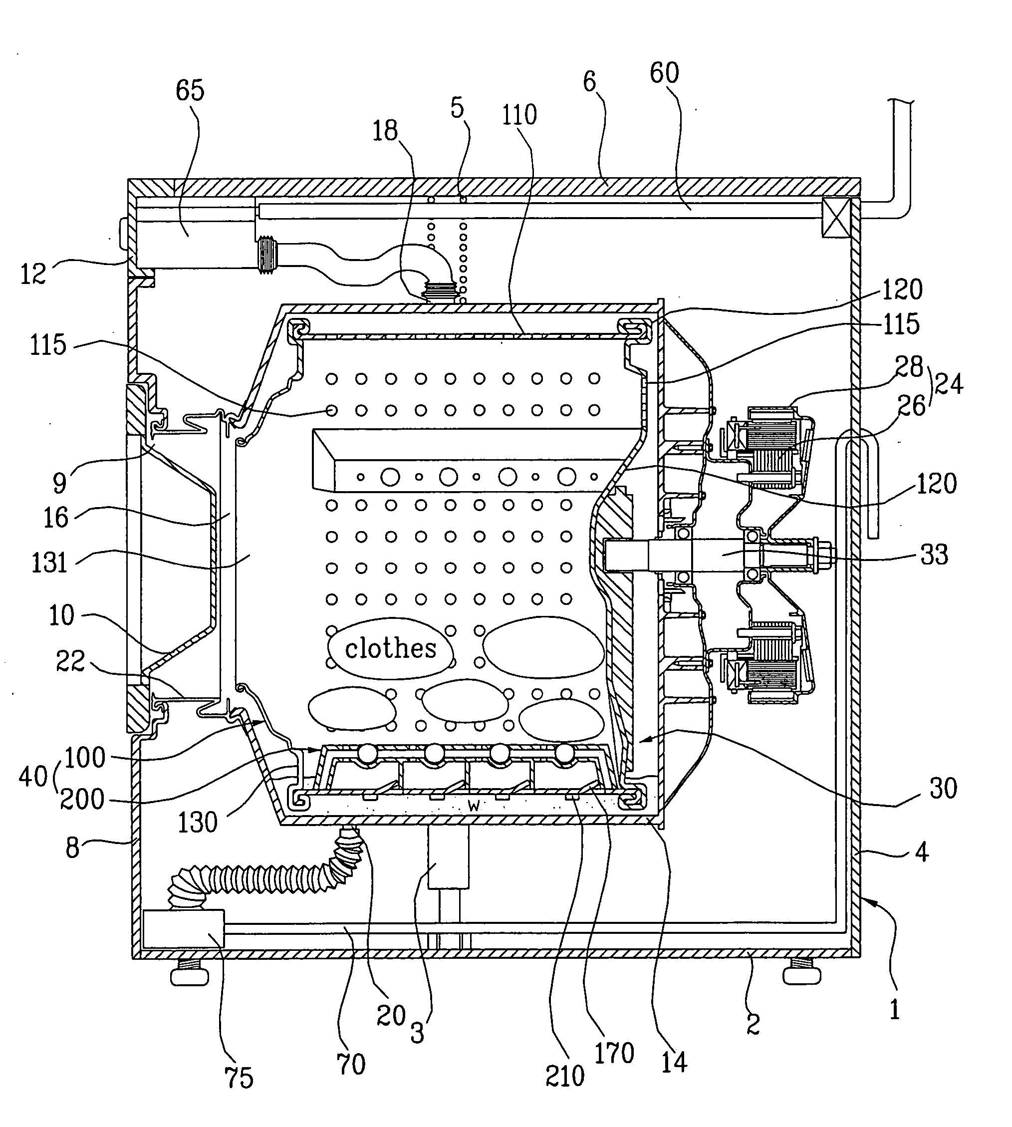
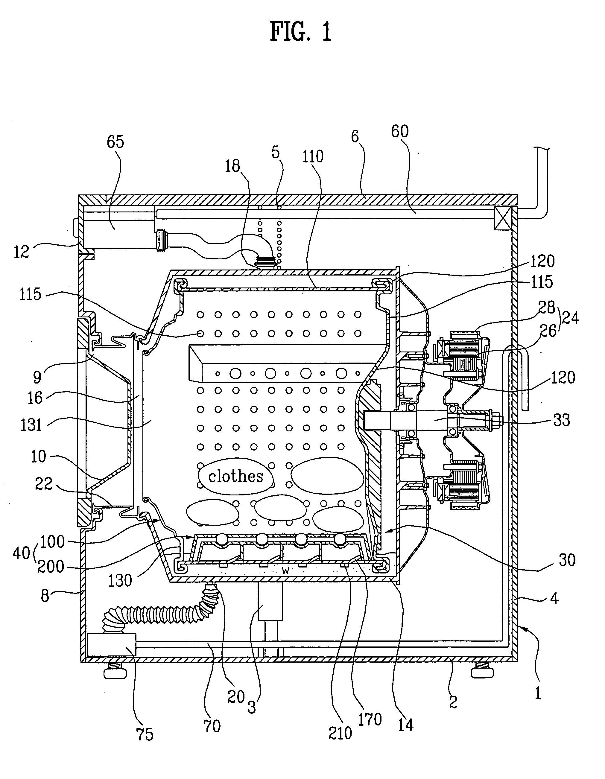
[0031] With reference to FIG. 1, a case 1 of the washing machine according to the present invention comprises a base plate 2, a wall 4, a top cover 6, and a front cover 8. The base plate 2 forms a bottom of the case 2, and the wall 4 is vertically mounted on the base plate 2, and forms a rear wall and both side walls of the washing machine according to the present invention. A top of the wall 4 is open, and a front of the wall is also open. And, the top cover 6 covers the open top of the wall 4, and the front cover 8 covers the open front of the wall 4. Further, there is a control panel 12 between a top of the front cover 8 and the top cover 6 so that the user can control the washing machine using the cont...


PUM


Abstract

A lifter is provided on a drum for lifting and dropping laundry in the drum during a rotation of the drum. The lifter slides and moves along an inner surface of the drum after passing through the inner surface so as to be engaged to the drum. At least one slot is provided on a circumference of the drum, and at least one hook is provided on the lifter for being engaged to the slot. Further, at least one projection is provided on the drum, and at least on rib is provided on the lifter. The projection and the rib are tightly engaged with each other so as to secure the lifter to the drum when the lifter completely slides and moves laterally.

Description

CROSS-REFERENCE TO RELATED APPLICATIONS [0001] This application claims the benefit of Korean Utility Model Application No. U2004-013533, filed on May 15, 2004, which is hereby incorporated by reference as if fully set forth herein. BACKGROUND OF THE INVENTION [0002] 1. Field of the Invention [0003] The present invention relates to a washing machine, and more particularly, to a drum assembly with lifters therein for lifting and dropping laundry to improve washing, rinsing, and dehydrating performances. [0004] 2. Discussion of the Related Art [0005] Washing machine is a representative home appliance for washing laundry using detergent and water. The washing machine is generally classified into two types, i.e., a top loading type and a front loading type based on the location of an opening for receiving the laundry. [0006] The top loading type washing machine generally comprises a vertical tub for accommodating the laundry, a pulsater rotating in the tub and washing the laundry, and a ...

Claims


Application Information

Patent Timeline
Patent Type & Authority Applications(United States)
IPC IPC(8): D06F21/00D06F37/06
CPCD06F37/06
Inventor AHN, BYUNG HWAN
Owner LG ELECTRONICS INC
Why Eureka
Try Eureka