Hydraulic suspension with a lock-out mechanism for an off-highway vehicle

a technology of lock-out mechanism and hydraulic suspension, which is applied in vehicle maintenance, transportation and packaging, vehicle cleaning apparatus, etc., can solve the problems of affecting the maneuverability of the vehicle, affecting the safety of the vehicle, and adding significantly to the cost of the suspension

Inactive Publication Date: 2005-11-17
HUSCO INT INC
View PDF7 Cites 20 Cited by
  • Summary
  • Abstract
  • Description
  • Claims
  • Application Information

AI Technical Summary

Benefits of technology

[0014] When the control valve is open, forces exerted on the suspension system cause the cylinder to compress and extend freely as the fluid is able to flow in both directions between the cylinder and the accumulator. The degree to which the control valve opens can be varied to alter the amount of motion damping provided by the cylinder. Closing the control valve places the suspension hydraulic circuit 30 in the locked-out state which replicates a suspension in which the axle is rigidly connected to the vehicle frame. Now fluid attempting to exit the second chamber is blocked from reaching the accumulator by the second check valve and the control valve. In this state, the first check valve and the control valve block any fluid attempting to exit the second chamber of the cylinder. As a consequence, the cylinder piston is unable to extend or retract in either direction and the position of the suspension remains stationary. This hydraulic circuit configuration enables engagement and disengagement of the lock-out function to be performed by a single control valve.

Problems solved by technology

A very heavy load forces the vehicle body downward with respect to the axles, which can adversely affect the maneuverability of the vehicle.
On the other hand, if the suspension is configured for relatively heavy loads, the vehicle may have an undesirable ride under lighter loads.
This multiple valve arrangement added significantly to the expense of the suspension.

Method used


Image

  • Hydraulic suspension with a lock-out mechanism for an off-highway vehicle
  • Hydraulic suspension with a lock-out mechanism for an off-highway vehicle

Examples


Embodiment Construction

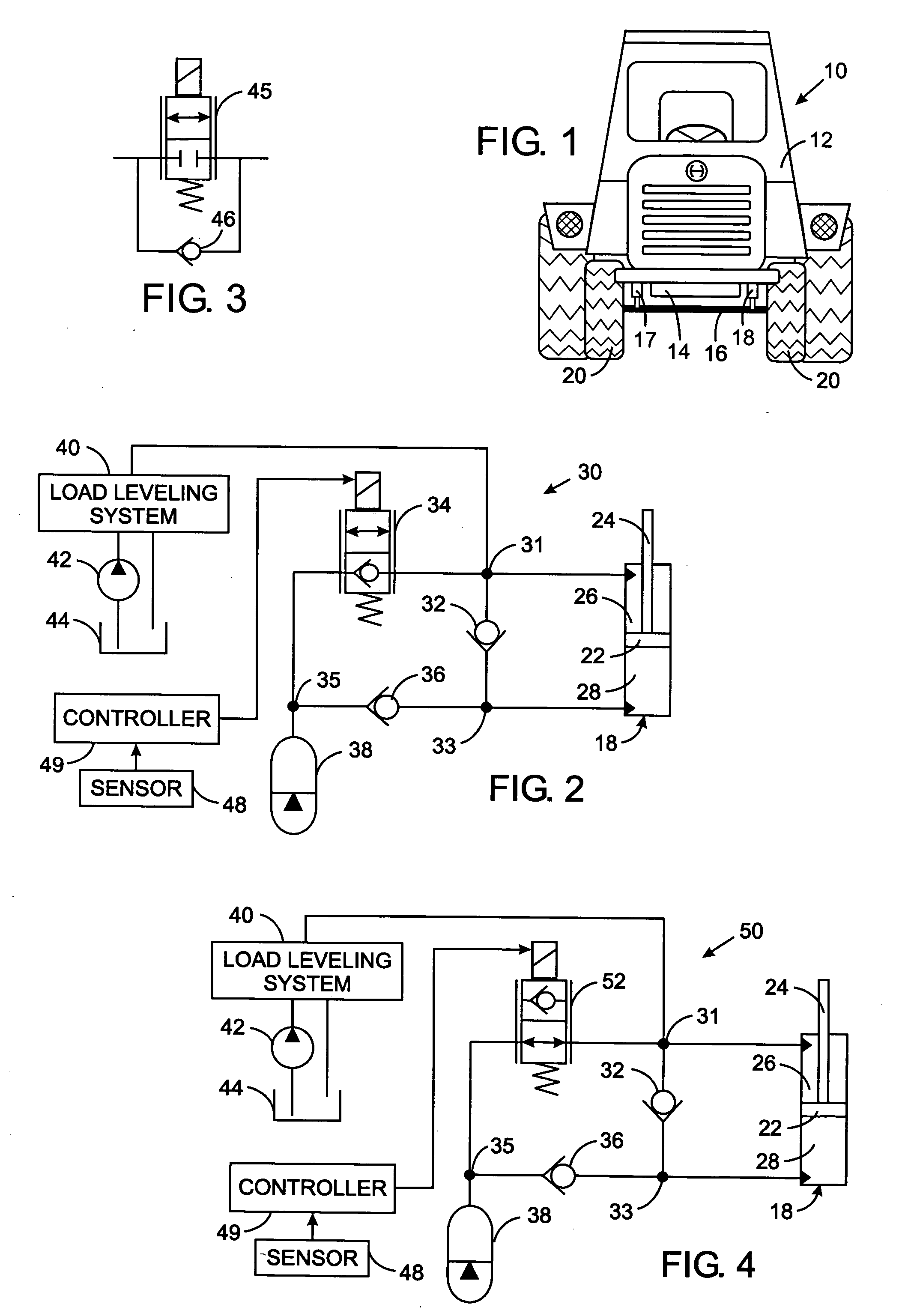
[0020] With initial reference to FIG. 1, an off-road vehicle 10, such as an agricultural tractor, has a body 12 with a frame 14 that is linked to axles to which the wheels of the vehicle are attached. For example, the front axle 16 is coupled to the frame 14 by a pair of hydraulic cylinders 17 and 18 and has a pair of front wheels 20 attached to it. As will be described, pressurized hydraulic fluid is applied to and drained from the cylinders 17 and 18 to control the distance that the body 12 of the tractor is above the front axle 16. This hydraulic system adjusts dynamically to ensure that a relatively constant separation distance exists regardless of the load applied to the vehicle 10.

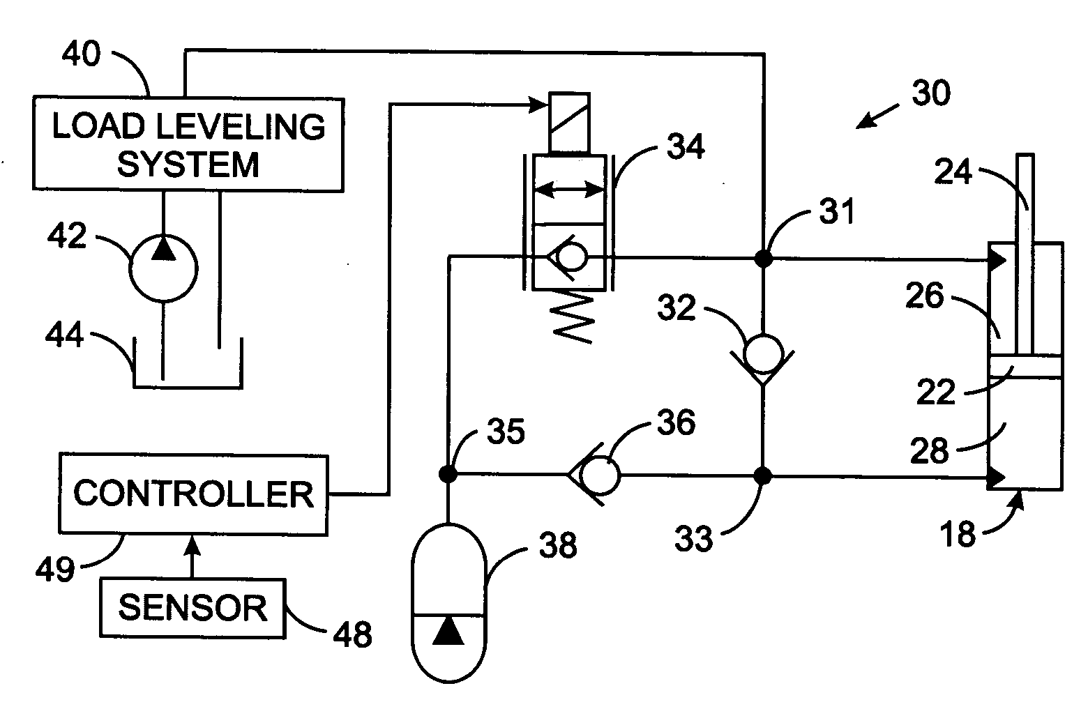
[0021] The control of the tractor suspension shall be described with respect to cylinder 18 with the understanding that the other cylinder 17 is controlled in the identical manner. Referring to FIG. 2, the cylinder 18 has an internal bore in which a piston 22 with a rod 24 is slidably received; ther...


PUM


Abstract

A vehicle has an axle connected to a frame by at least one hydraulic cylinder with two chambers separated by a piston. A hydraulic circuit controls flow of fluid between two cylinder chambers and between the chambers and an accumulator to dampen motion of the frame relative to the axle. The hydraulic circuit includes a control valve and a pair of check valves arranged so that the single control valve is able to lock-out the cylinder to emulate a rigid connection of the frame to the axle, as needed.

Description

CROSS-REFERENCE TO RELATED APPLICATIONS [0001] Not Applicable STATEMENT REGARDING FEDERALLY SPONSORED RESEARCH OR DEVELOPMENT [0002] Not Applicable BACKGROUND OF THE INVENTION [0003] 1. Field of the Invention [0004] The present invention relates to suspension systems for off-road vehicles, such as those used in agricultural and construction businesses, and more particularly to adjustable hydraulically controlled suspension systems. [0005] 2. Description of the Related Art [0006] Off-road vehicles, such as construction and agricultural equipment, carry a wide range of loads over different types of surfaces. Thus, the suspension systems between the wheels and the frame of these vehicles are important for optimum operator comfort, productivity and safety. The suspension system must be adjustable depending upon the weight of the load applied to the equipment. A very heavy load forces the vehicle body downward with respect to the axles, which can adversely affect the maneuverability of t...

Claims


Application Information

Patent Timeline
Patent Type & Authority Applications(United States)
IPC IPC(8): B60G17/00B60G17/015B60G17/018
CPCB60G17/0152B60G17/018B60G2800/014B60G2400/61B60G2300/082
Inventor SCHEDGICK, DAVID JAMESBLOTZ, DOUGLAS CARLRADES, MATTHEW JAMES
Owner HUSCO INT INC
Why Eureka
Try Eureka