Flow control valve

a flow control and valve technology, applied in the direction of diaphragm valves, valve details, valve arrangements, etc., can solve the problems of not being able to conduct remote and high-precision control, and achieve the effect of preventing outflow

Inactive Publication Date: 2005-11-17
CKD
View PDF6 Cites 34 Cited by
  • Summary
  • Abstract
  • Description
  • Claims
  • Application Information

AI Technical Summary

Benefits of technology

[0021] The present invention has a second object to provide a flow control valve which controls a flow rate by pressure of compressed air against an urging force of a spring, and which can prevent an outflow of a controlled fluid during de-energization.
[0043] In the case where the flow control valve of the present invention is used in the semiconductor manufacturing device, which requires accurate flow control or the like, the above mentioned effects can largely be enhanced.

Problems solved by technology

Accordingly, it could not be conducted by remote and high-precision control.
Especially, if the outflow of the controlled fluid is continued during de-energization, the flow control valve 100 of FIG. 5 would be unusable in the semiconductor manufacturing device which requires accurate flow control.

Method used


Image

  • Flow control valve
  • Flow control valve
  • Flow control valve

Examples


first embodiment

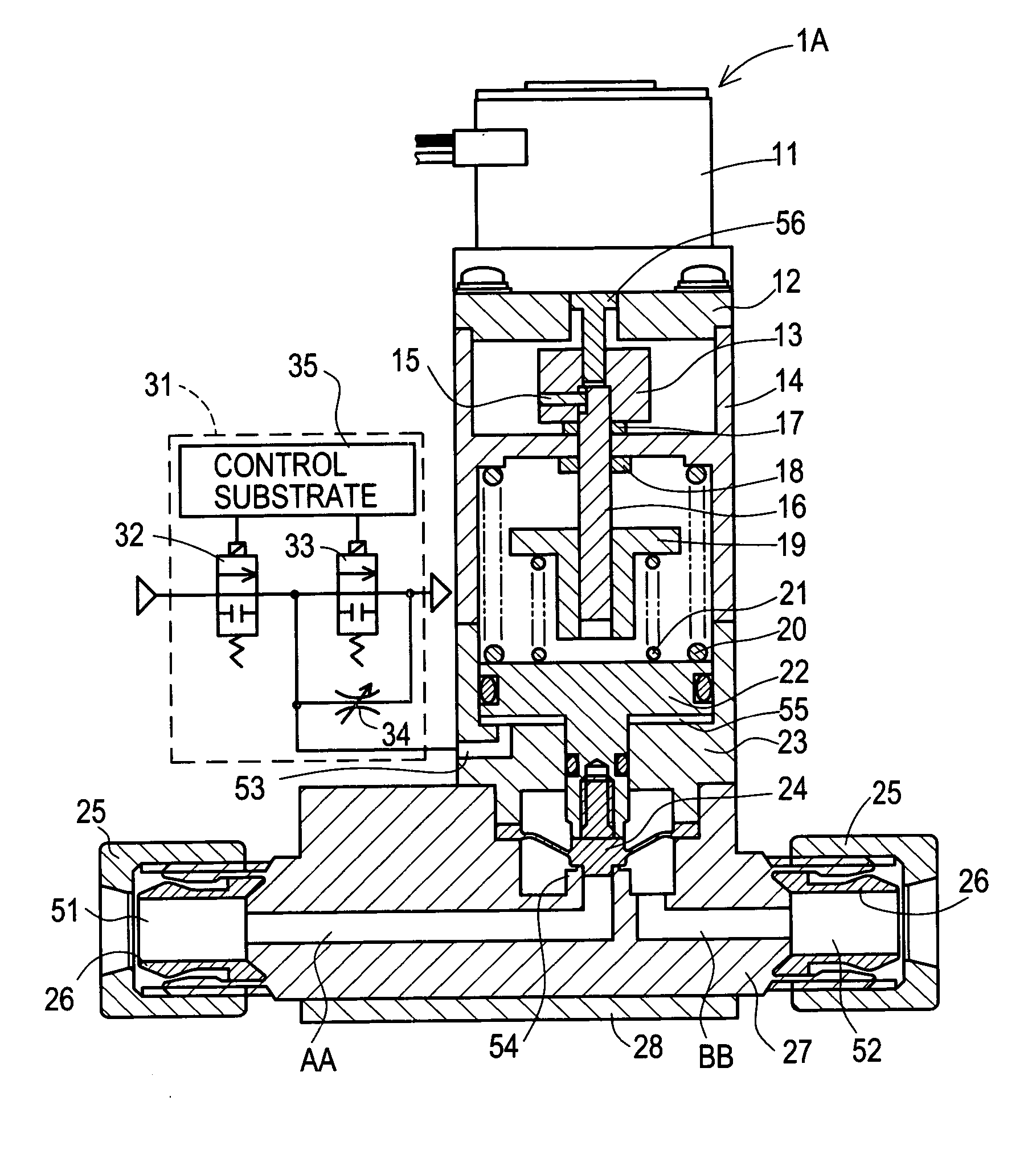
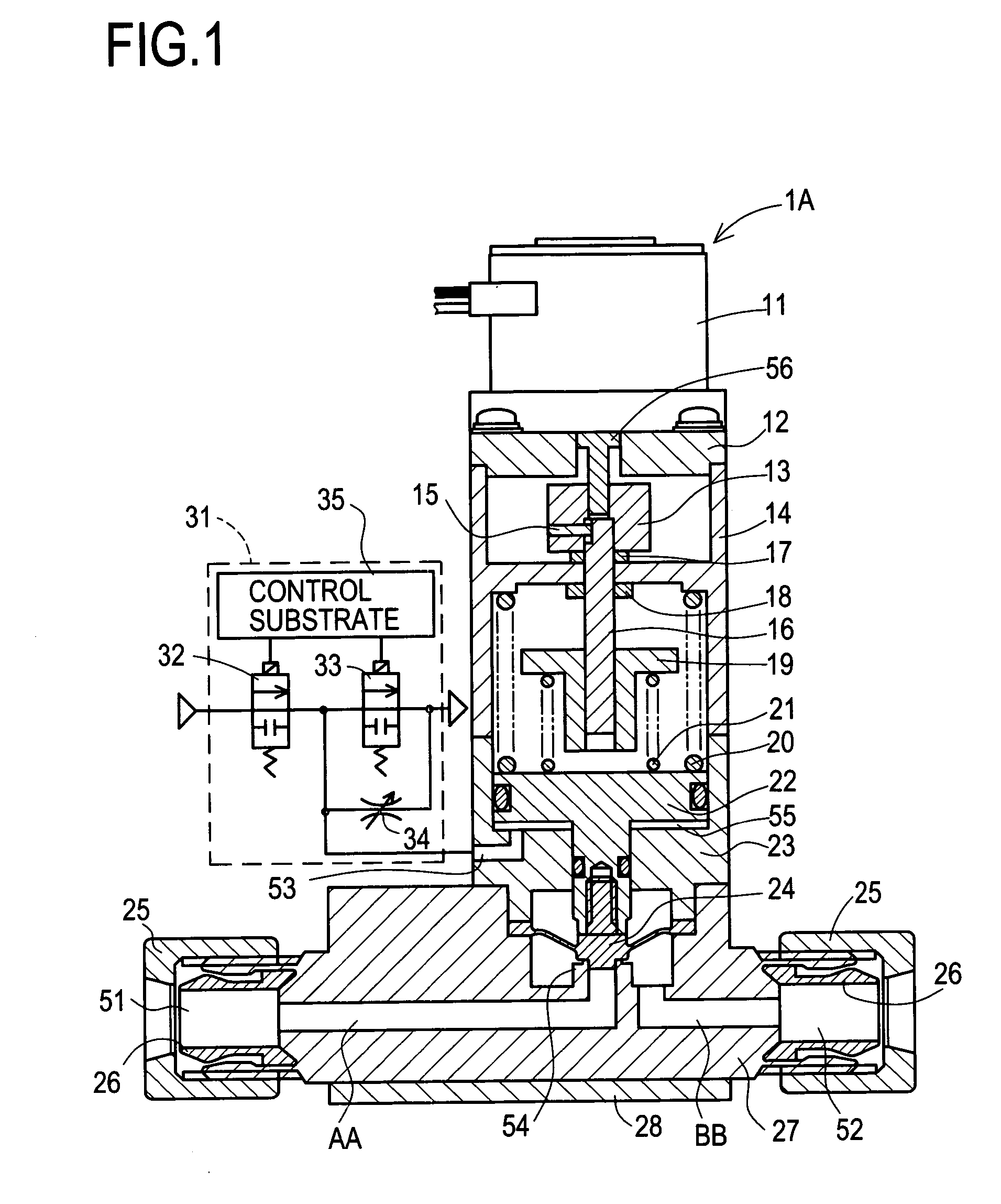
[0056] In other words, in the flow control valve 1A in the first embodiment, the servo motor 11, shaft 56, coupling 13, pin 15, thrust bearings 17 and 18, shaft 16, and others constitute a “motor driving control mechanism”.

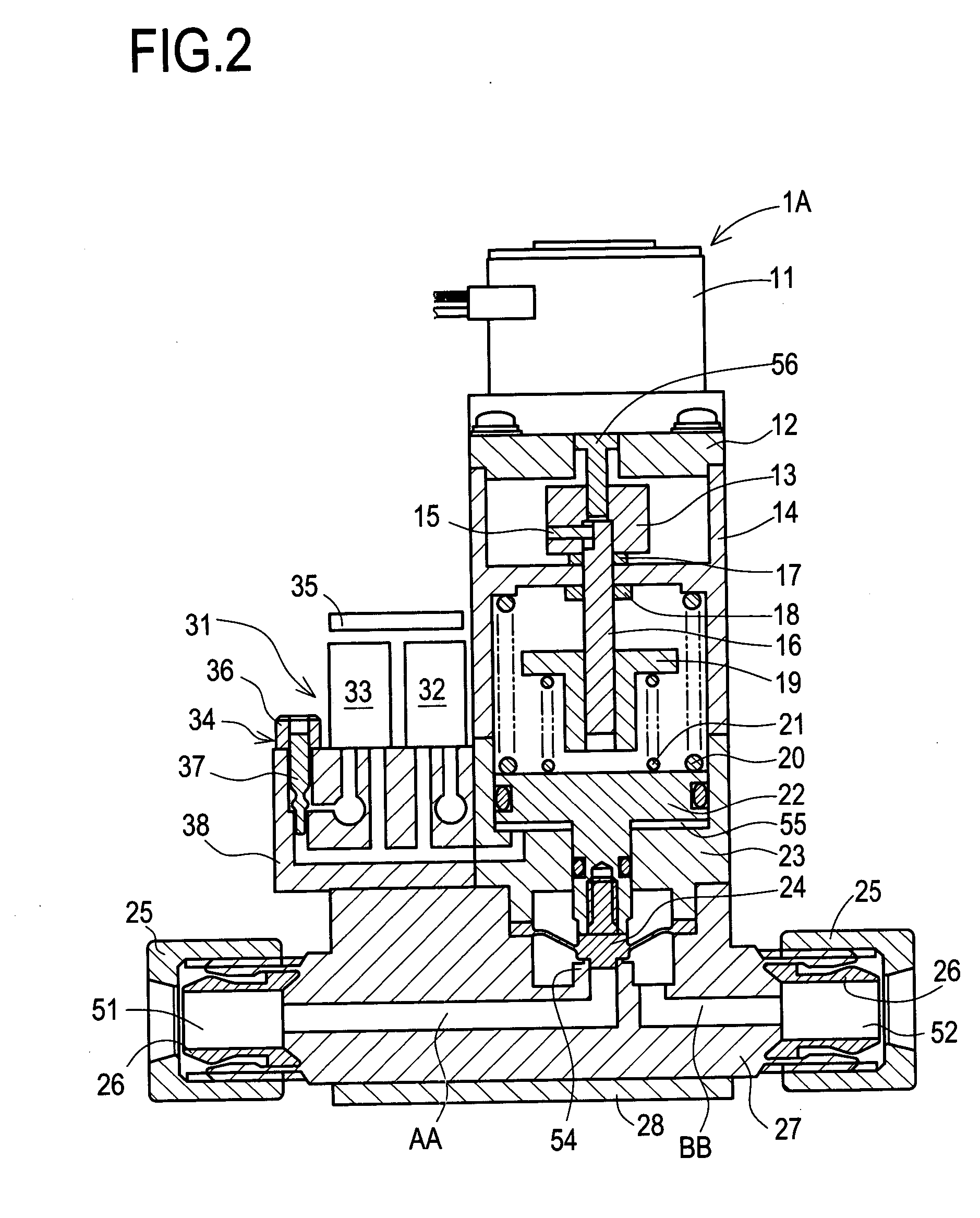
[0057] In the flow control valve 1A in the first embodiment, an electro-pneumatic regulator 31 is attached to the operation port 53 formed in the cylinder 23. This electro-pneumatic regulator 31 serves to control a normally-closed proportional intake valve 32 and a normally-closed proportional discharge valve 33 through a control substrate 35, and is also provided with a needle valve 34 (corresponding to a “bleeding mechanism”) which is manually operated. To be more concrete, as shown in FIG. 2, the proportional intake valve 32, the proportional discharge valve 33, and the needle valve 34 are attached to a passage block 38 in which a supply passage and a discharge passage are formed.

[0058] It is to be noted that the needle valve 34 serves to permit communication ...

second embodiment

[0080] The flow control valve 1B in the second embodiment is constructed so that, in the closed state, the diaphragm 24 is in close contact with the valve seat 54 by the urging force of the return spring 20. In this state, when the compressed air is supplied into the pilot chamber 55, the pressure of the compressed air exceeds the urging force of the return spring 20, and therefore the diaphragm 24 is brought out of contact with the valve seat 54, establishing the opened state. Further, there is provided the electro-pneumatic regulator 41 which controls the normally-closed proportional intake valve 42, the normally-closed proportional discharge valve 43, and the normally-opened proportional discharge valve 44 through the control substrate 45. During de-energization, the compressed air is allowed to be continuously discharged little by little from the inside of the pilot chamber 55, while the valve is changed to the closed state and held in the closed state. It is accordingly possibl...


PUM


Abstract

There is disclosed a flow control valve which regulates a flow rate by determining a stop position of a piston by contact in an opened state, and which enables remote and high-precision flow rate regulation. In a closed state, an urging force of a return spring acts on a piston, bringing a diaphragm into close contact with a valve seat. In this state, when compressed air is supplied into a pilot chamber, moving the piston, the diaphragm is brought out of contact with the valve seat. Then, the piston comes into contact with a nut and the diaphragm is stopped providing a fixed clearance between the diaphragm and the valve seat. An opened state is established. Of course, the nut can be moved to any desired position by means of a serve motor or the like, so that a position at which the piston comes into contact with the nut can be changed.

Description

CROSS-REFERENCE TO RELATED APPLICATIONS [0001] This application is a continuation application based upon and claims the benefit of the prior PCT International Patent Application No. PCT / JP03 / 02758 filed on Mar. 7, 2003, the entire contents of which are incorporated herein by reference.BACKGROUND OF THE INVENTION [0002] 1. Field of the Invention [0003] The present invention relates to a flow control valve which is changed to and held in an opened state by pressure of compressed air against an urging force of a spring and more particularly to a flow control valve for use in a semiconductor manufacturing device. [0004] 2. Description of Related Art [0005] As one of conventional flow control valves, for example, there is a flow control valve disclosed in Japanese unexamined patent publication No. 7(1995)-253170. FIG. 4 is a sectional view of such flow control valve 100. This flow control valve 100 has an under body 120 with an inlet port 121 and an outlet port 122 formed on either side....

Claims


Application Information

Patent Timeline
Patent Type & Authority Applications(United States)
IPC IPC(8): F16K1/52F16K7/17F16K31/124
CPCF16K1/523F16K31/1245F16K7/17
Inventor YASUE, HIROTOHIRAKO, YASUSHIKAGOHASHI, HIROSHISUGATA, KAZUHIRO
Owner CKD
Why Eureka
Try Eureka