Laminated-type piezoelectric element and inkjet recording head having the same

a piezoelectric element and inkjet technology, applied in piezoelectric/electrostrictive/magnetostrictive devices, piezoelectric/electrostriction/magnetostriction machines, printing, etc., can solve the problems of poor quality of recording head and screen recording of each product, inability to accurately set the length lb>4/b> of active portions, etc., to achieve stabilization in the quality of recording head and print quality, the effect o

Active Publication Date: 2005-11-17
BROTHER KOGYO KK
View PDF16 Cites 44 Cited by
  • Summary
  • Abstract
  • Description
  • Claims
  • Application Information

AI Technical Summary

Benefits of technology

[0018] According to this structure, if the inkjet recording head is manufactured with using such a laminated-type piezoelectric element, a deviation in ink eject speed from nozzles is decreased when the same activating voltage is applied to, resulting in a stabilization in quality of a recording head and in print quality.

Problems solved by technology

However, even though the individual electrode 103 and the common electrode 106 are manufactured to have patterns without positional deviances in the X direction during the screen printing, if the piezoelectric sheet 102 having the individual electrode 103 and the piezoelectric sheet 105 having the common electrode 106 laminated on each other are deviated to the X direction on a plane perpendicular to the laminated direction, it is not possible to accurately set the length L4 of the active portions.
This results in poor quality of the recording head and screen recording of each product.

Method used


Image

  • Laminated-type piezoelectric element and inkjet recording head having the same
  • Laminated-type piezoelectric element and inkjet recording head having the same
  • Laminated-type piezoelectric element and inkjet recording head having the same

Examples


Embodiment Construction

[0031] Hereinafter, preferred embodiments of the invention will be described with reference to the accompanying drawings.

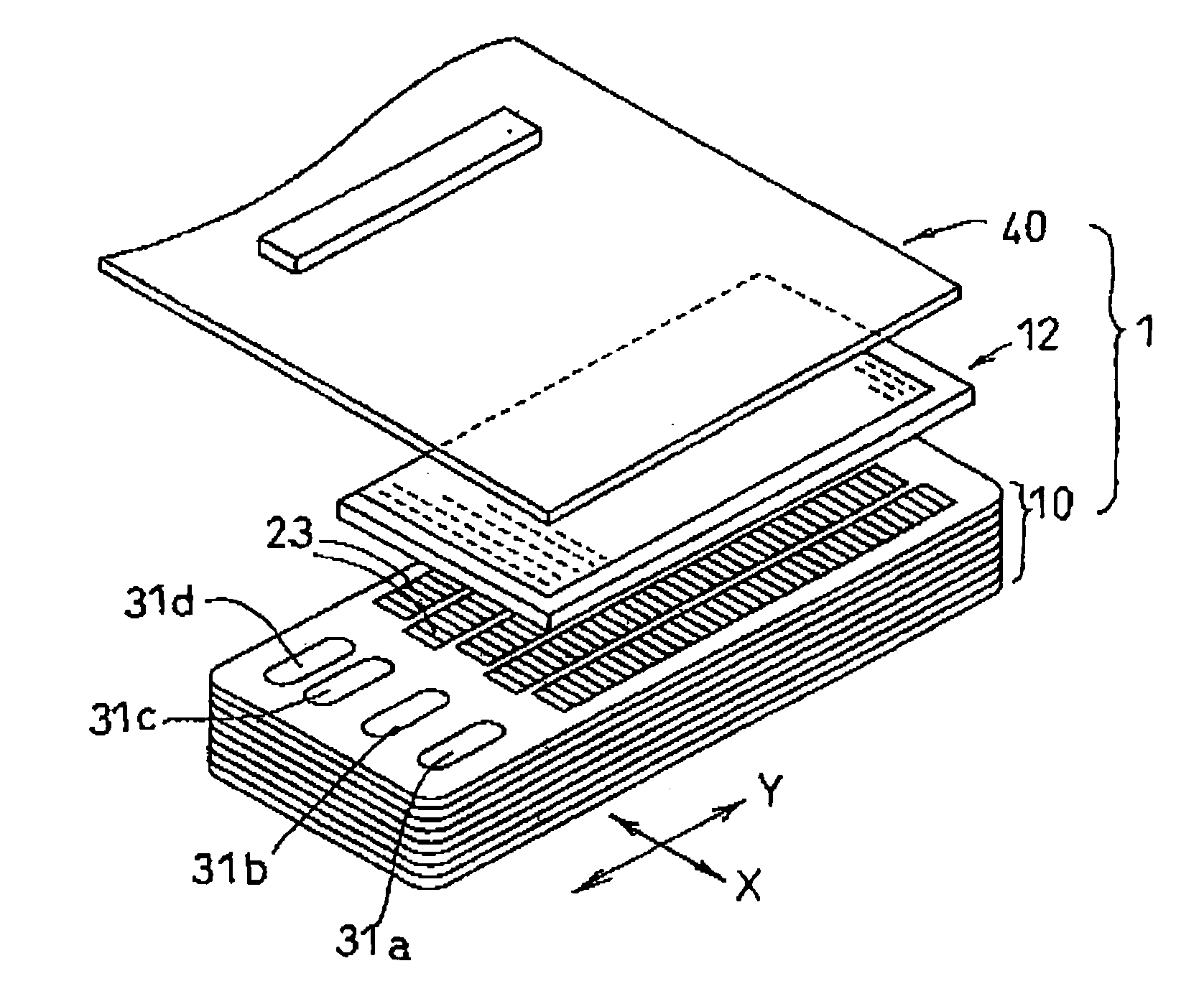
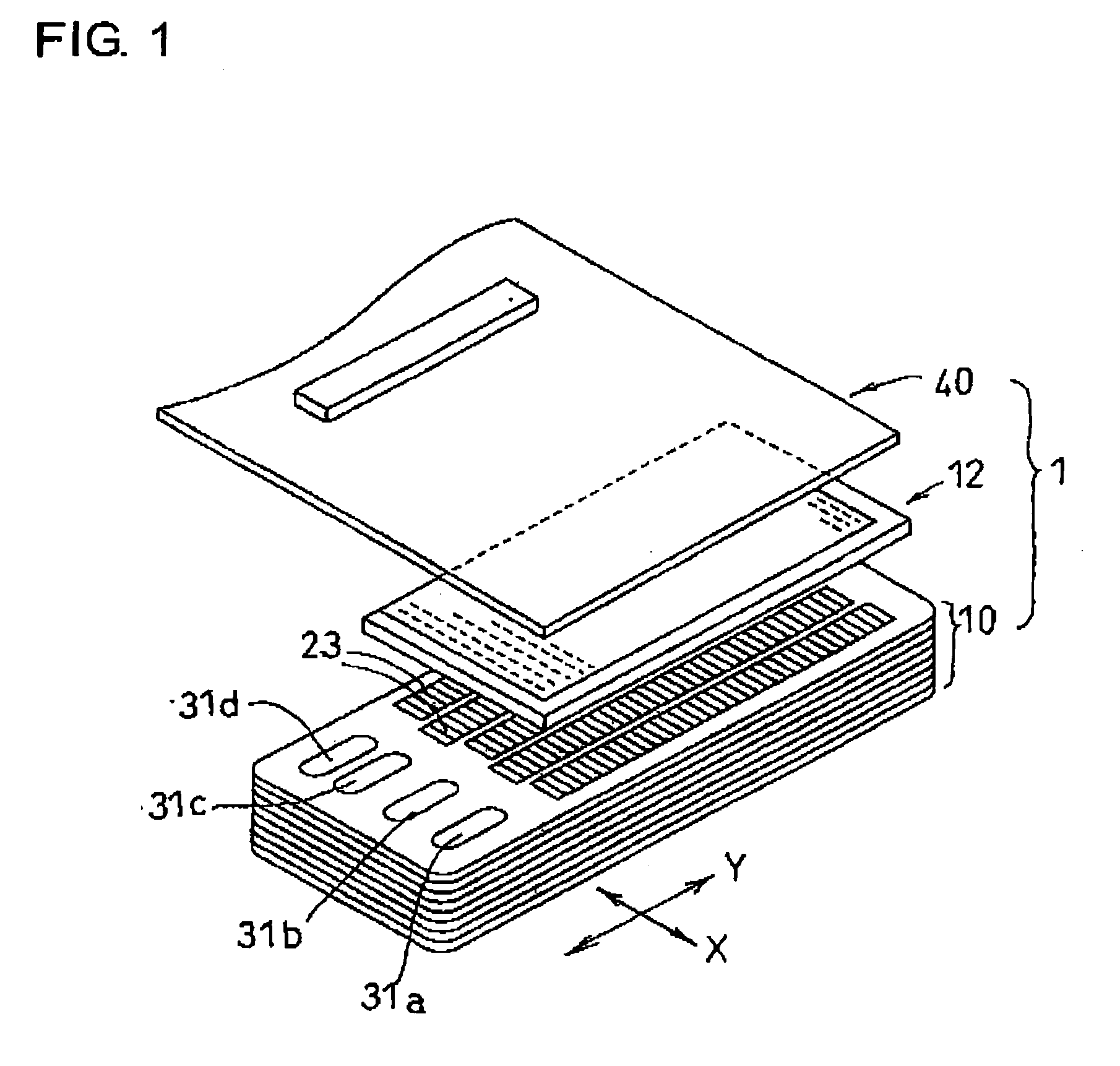
[0032] An inkjet recording head for color print according to this embodiment includes a head unit 1 mounted on a carriage (not shown) reciprocating in a direction (main-scanning direction, hereinafter referred to as a first direction or X direction) perpendicular to a paper conveyance direction (sub-scanning direction, hereinafter referred to as a second direction or Y direction). Ink cartridges filled with four color inks including, for example, cyan, magenta, yellow, and black inks, respectively, are detachably mounted in the head unit 1. Alternately, each color ink is supplied from each ink cartridge mounted on a main body of an image forming device through a supply pipe (not shown) and a damper chamber (not shown) mounted on the carriage.

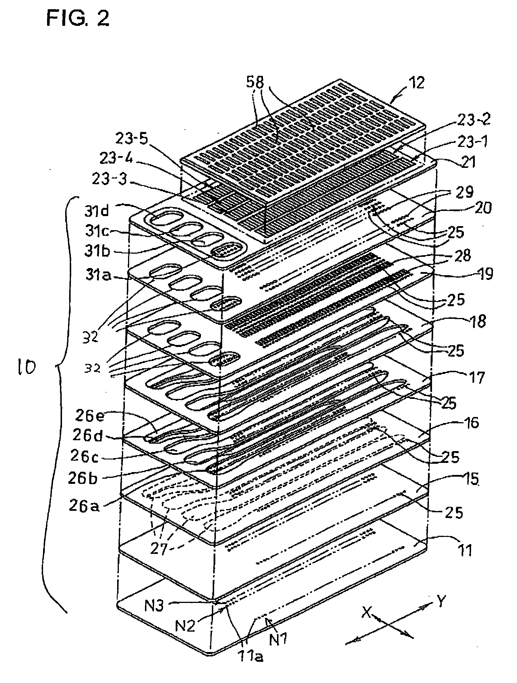
[0033] As shown in FIG. 2, the head unit 1 includes a cavity unit 10, a plate-type piezoelectric actuator 12, and a flexib...


PUM


Abstract

A laminated-type piezoelectric element includes first electrode layers defining individual electrodes, second electrode layers defining common electrodes, and piezoelectric sheets sandwiched between the first and second electrode layers. The first and second electrode layers are laminated alternately. Each individual electrode has a substantially rectangle shape extending in a first direction. The individual electrodes defined in each first electrode layer are arranged at predetermined intervals in a second direction perpendicular to the first direction, to form a row. The common electrode includes a first portion having a band shape. The first portion overlaps the row when viewed in a plan view. The first portion has a pair of edges extending to be perpendicular to a long side of the rectangle shape of each individual electrode. Both ends of each individual electrode in the first direction protrude to outer positions than the edges, when viewed in the plan view.

Description

BACKGROUND OF THE INVENTION [0001] 1. Field of the Invention [0002] The present invention relates to a laminated-type piezoelectric element and an inkjet recording head having the same. [0003] 2. Description of the Related Art [0004] Conventionally, a piezoelectric element has been used as a driving source (piezoelectric actuator) used for various types of devices with utilizing its characteristics of converting electric energy into mechanical displacement (deformation) by piezoelectric effects. [0005] Of the piezoelectric elements, a piezoelectric element, which is formed into a laminated type in order to increase a deformation amount due to distortion, has the following structure. Individual electrodes and common electrodes are formed on one surface (one broad surface) of a piezoelectric sheet made of ceramic material such as PZT (lead zirconate titanate) by the screen printing method with using conductive material such as conductive paste. Piezoelectric sheets having the common e...

Claims


Application Information

Patent Timeline
Patent Type & Authority Applications(United States)
IPC IPC(8): B41J2/055B41J2/045B41J2/14H01L41/047H01L41/083
CPCB41J2/14209B41J2002/14217B41J2002/14225H01L41/0474H01L41/083H01L41/0471B41J2002/14491H10N30/874H10N30/871H10N30/50
Inventor ITO, ATSUSHI
Owner BROTHER KOGYO KK
Why Eureka
Try Eureka