Delay locked loop circuit and method for testing the operability of the circuit

a technology of lock loop circuit and lock loop circuit, which is applied in the direction of time-delay network, pulse automatic control, instruments, etc., can solve the problems of inability to test the delay element to determine whether any of the delay elements have malfunctioned, and the tap selector cannot be tested to determine whether

Active Publication Date: 2005-11-17
AVAGO TECH INT SALES PTE LTD
View PDF10 Cites 8 Cited by
  • Summary
  • Abstract
  • Description
  • Claims
  • Application Information

AI Technical Summary

Benefits of technology

[0005] A delay locked loop (DLL) circuit and method for testing the operability of the circuit utilizes one or more test signal sources and a test signal receiver to selectively transmit test signals, for example, static test...

Problems solved by technology

A concern with the conventional DLL circuit is that the delay elements cannot be tested to determine whether any of the delay elements has malfunction...

Method used


Image

  • Delay locked loop circuit and method for testing the operability of the circuit
  • Delay locked loop circuit and method for testing the operability of the circuit
  • Delay locked loop circuit and method for testing the operability of the circuit

Examples


Embodiment Construction

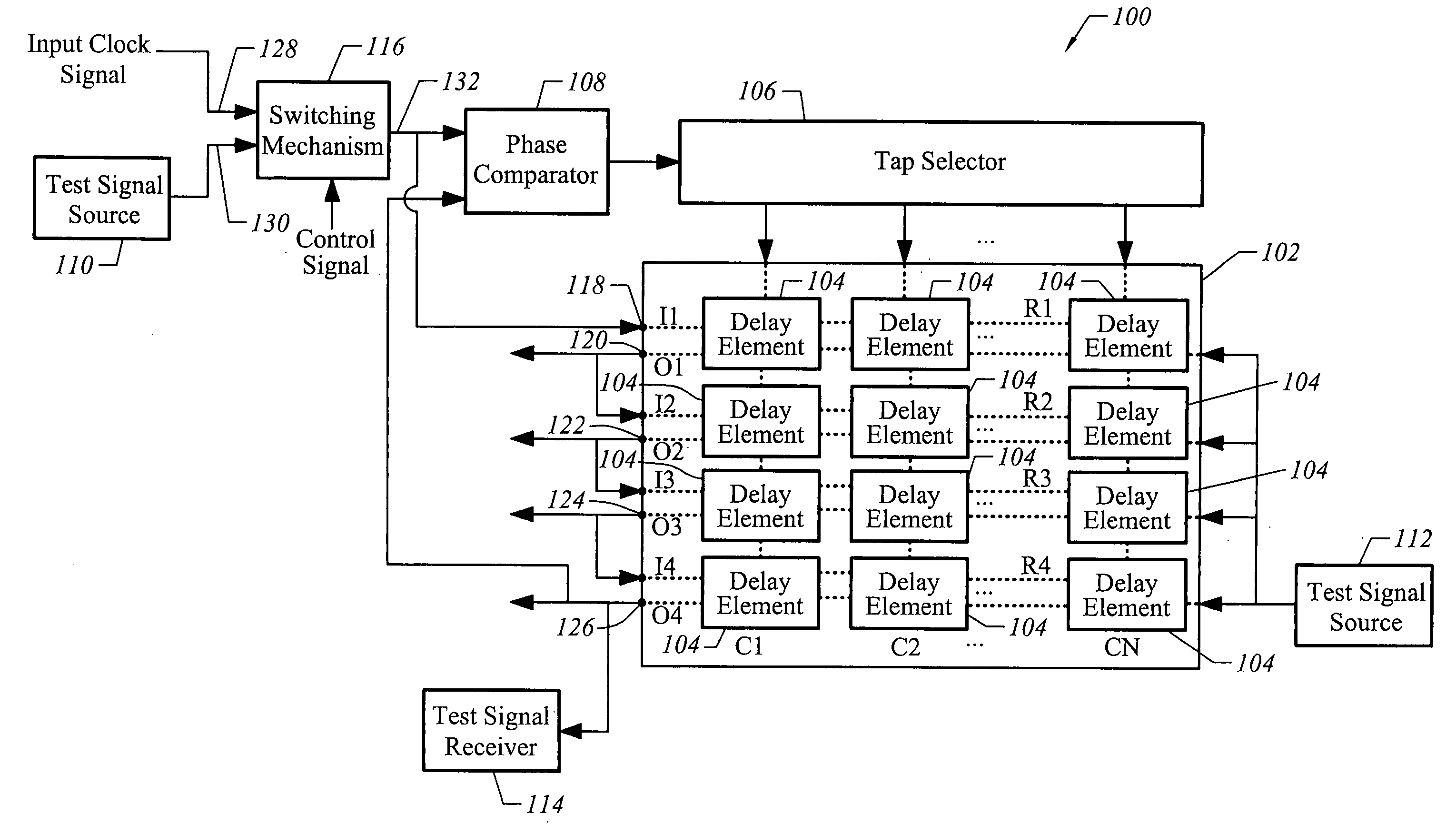
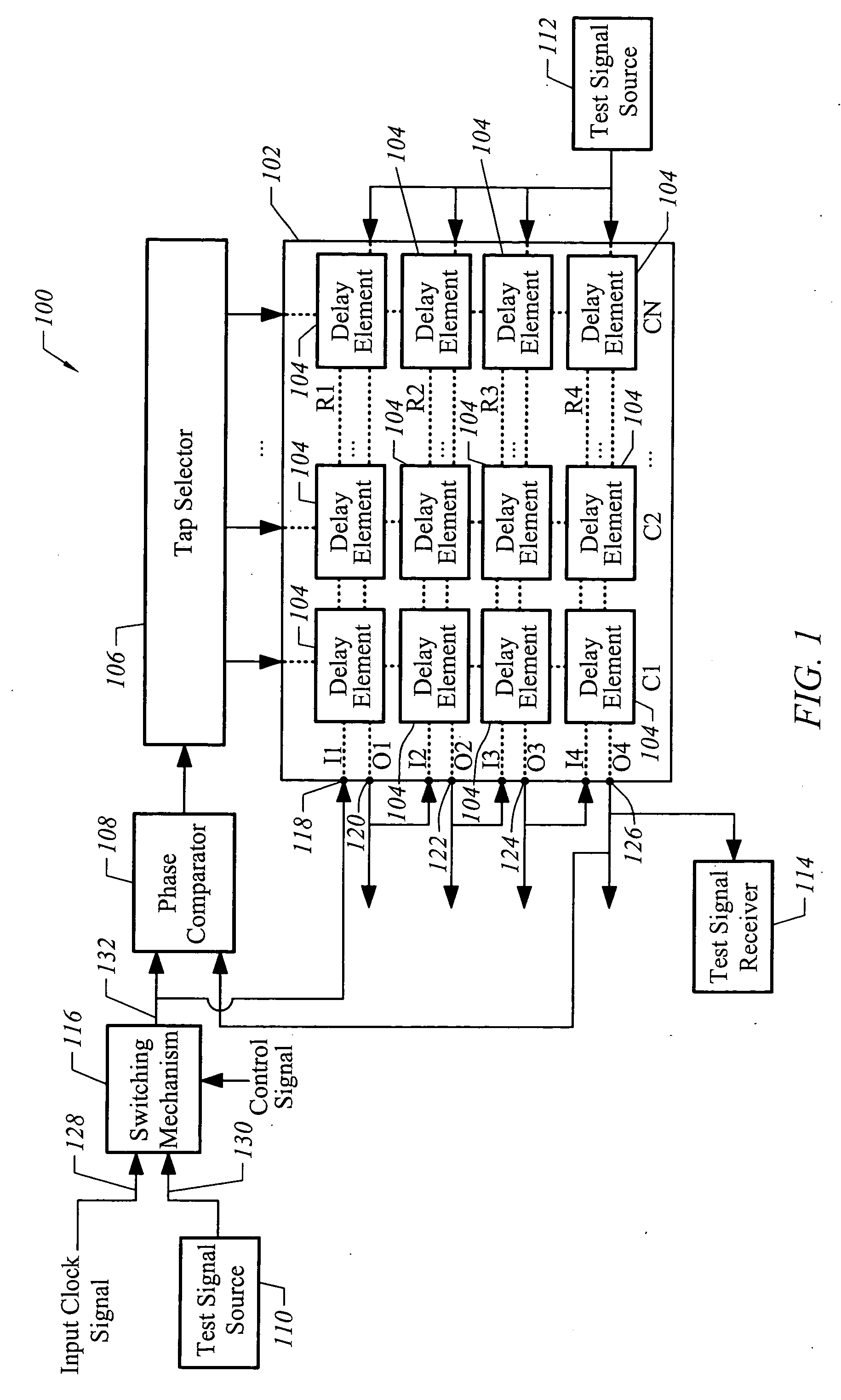
[0013] With reference to FIG. 1, a Delay Locked Loop (DLL) circuit 100 in accordance with an embodiment of the invention is described. The DLL circuit 100 is designed with testability considerations, and thus, includes a test for operating feature, at minimal cost for additional test hardware resources. Consequently, the DLL circuit 100 can be tested for operability prior to being integrated into a larger system. The DLL circuit 100 can be used to generate multiple output clock signals with alternate signal edges using an input clock signal for use in storage devices, such as Double Data Rate (DDR) memories. However, the DLL circuit 100 can be used for other applications in which multiple output clock signals with alternate signal edges are required.

[0014] As shown in FIG. 1, the DLL circuit 100 includes an array 102 of delay elements 104, a tap selector 106 and a phase comparator 108. These components are used during a normal operational mode of the DLL circuit 100 to output phase...


PUM


Abstract

A delay locked loop (DLL) circuit and method for testing the operability of the circuit utilizes one or more test signal sources and a test signal receiver to selectively transmit test signals, for example, static test signals, through an array of delay elements of the DLL circuit. The resulting output signals of the array are used to determine whether any delay element or a tap selector of the DLL circuit has malfunctioned, e.g., stuck-at fault.

Description

BACKGROUND OF THE INVENTION [0001] Delay Locked Loop (DLL) circuits are used to generate one or more output clock signals with alternate signal edges from an input clock signal. DLL circuits are commonly used to provide high-frequency clock signals to support storage devices, such as Double Data Rate (DDR) memories. DLL circuits are also commonly used in serial interfaces such as in networking components. [0002] A conventional DLL circuit of interest includes an array of identical delay elements, a phase comparator and a tap selector. The array of delay elements includes M rows (e.g., M=4) and N columns (e.g., N=64) of delay elements. The delay elements are configured such that the delay elements can be set to form an adjustable delay chain. The adjustable delay chain of delay elements allow an input clock signal to be routed through selected delay elements to produce output signals that are phase-shifted by predefined degrees at different locations along the delay chain. The delay ...

Claims


Application Information

Patent Timeline
IPC IPC(8): G01R23/175H03H11/26H03L7/081
CPCH03L7/0814H03L7/0816
Inventor CHIN, RICHARD
Owner AVAGO TECH INT SALES PTE LTD
Why Eureka
Try Eureka