

Power generation circuit using electromagnetic wave
a power generation circuit and electromagnetic wave technology, applied in the field of circuits, can solve the problems of changing the characteristics of the antenna, the need for supplying electric power,
- Summary
- Abstract
- Description
- Claims
- Application Information
AI Technical Summary
Benefits of technology
Problems solved by technology
Method used
Image

Examples
first embodiment
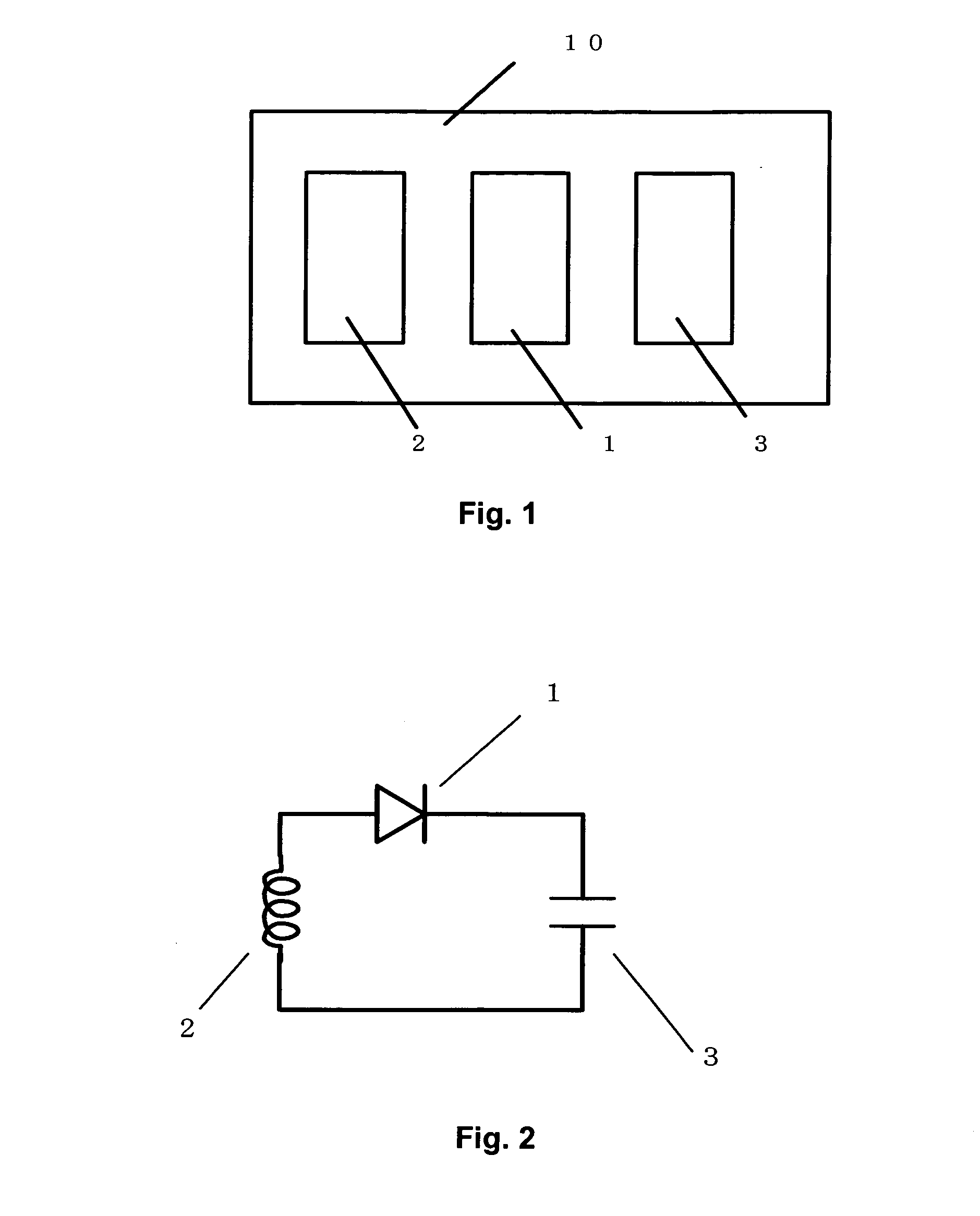
[0032]FIG. 1 is a power generation circuit using electromagnetic wave according to a first embodiment of the present invention.
[0033] An antenna or a coil 2, a rectifying circuit 1, and a storage circuit 3 are mounted on a substrate 10. A capacitor, for example, may be used instead of the storage circuit 3.
[0034]FIG. 2 shows a specific example of a power generation circuit using electromagnetic wave. A coil 2-serving as the antenna 2, a Schottkey barrier diode (hereinafter called “SBD”) serving as the rectifying circuit 1 and a capacitor 3 serving as the storage circuit 3 are connected therebetween.
[0035] The coil 2 receives the energy supplied from a commercially available electromagnetic wave such as an electromagnetic wave for a cellular telephone, TV broadcasting, or FM radio broadcasting. The SBD1 rectifies a voltage generated in the coil 2 to inject electric charge into the capacitor 3.
[0036] Kind and strength of the commercially available electromagnetic wave differ great...
second embodiment
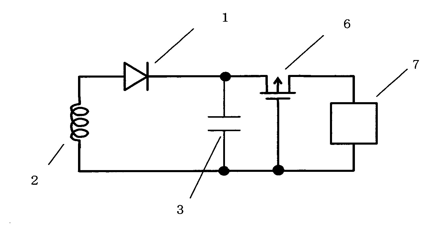
[0037]FIG. 3 is a power generation circuit using electromagnetic wave according to a second embodiment of the present invention.
[0038] A coil 2, a SBD 1, and a capacitor 3 are connected similar to those of FIG. 2. A source of a P-channel MOS transistor 6 is connected to a positive terminal of the capacitor 3, and a drain of the P-channel MOS transistor 6 is connected to a load 7. A gate of the MOS transistor 6 is connected to a negative terminal of the capacitor 3.
[0039] Connecting in this way, the MOS transistor 6 turns onto connect the load 7 to the capacitor 3 in parallel and the energy of the capacitor 3 can drive the load 7 when the voltage accumulating in the capacitor 3 becomes higher than the threshold voltage of the MOS transistor 6.
[0040] The MOS transistor 6 is in an off-state when the voltage of the stored charge in the capacitor 3 is less than the threshold voltage of the MOS transistor 6, and no electric power is consumed. In this circuit detection of the voltage ac...
third embodiment
[0045]FIG. 7 is a power generation circuit using electromagnetic wave according to a third embodiment of the present invention.
[0046] A rectifying circuit and elements such as a-capacitor, a resistor, or a MOS transistor are fabricated on a silicon substrate 50 by silicon planar process. In addition, a recess is formed in the silicon substrate 50 by anisotropic dry etching of silicon such as deep reactive ion etching (DRIE), or by anisotropic wet etching employing a material such as tetramethylammonium hydroxide (TMAH). When the recess is formed by DRIE, the recess is formed substantially perpendicular with respect to the silicon substrate, as shown in FIG. 7. When the recess is formed by wet etching, the recess is generally formed with a certain angle with respect to the substrate.
[0047] On the other hand, there is a projecting terminal on the antenna 2. The projecting terminal is inserted into the recess of the silicon substrate 50. The depth and the size of the recess of the si...
PUM
 Abstract
Description
Claims
Application Information