Air flow direction neutral heat transfer device

a technology of heat transfer device and air flow direction, which is applied in semiconductor devices, lighting and heating apparatus, cooling/ventilation/heating modifications, etc., can solve the problems of limited heat sink size and unfavorable arrangemen

Inactive Publication Date: 2005-11-17
HEWLETT PACKARD DEV CO LP
View PDF22 Cites 18 Cited by
  • Summary
  • Abstract
  • Description
  • Claims
  • Application Information

AI Technical Summary

Problems solved by technology

Often, the heat sink size is limited by the available space on a circuit board or other circuit mounting structure.
These arrangements have not been particularly effective.

Method used


Image

  • Air flow direction neutral heat transfer device
  • Air flow direction neutral heat transfer device
  • Air flow direction neutral heat transfer device

Examples


embodiment 31

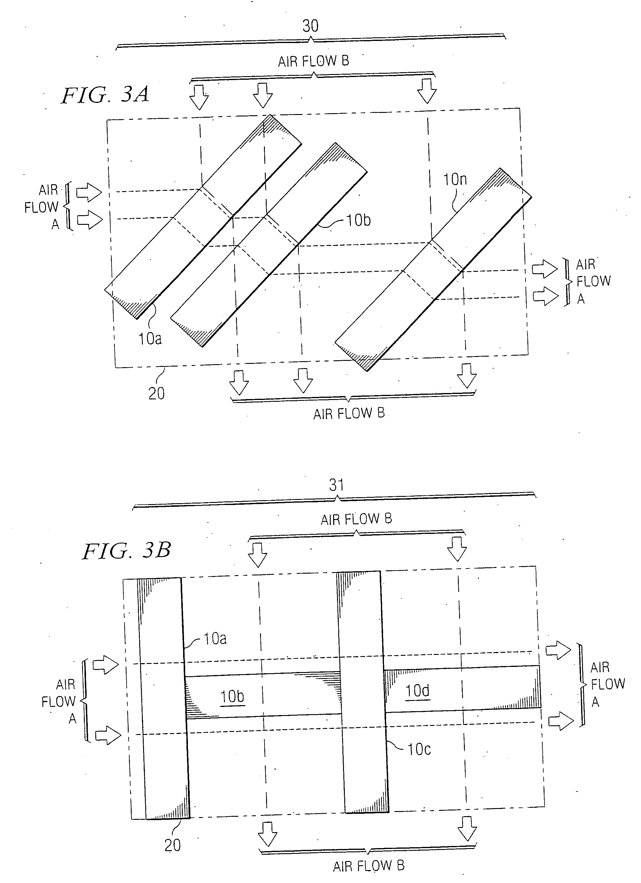
[0013]FIG. 3B illustrates embodiment 31 in which heat sinks 10a and 10c have cooling air moving there through in the A direction. Heat sinks 10b and 10d, which are angularly displaced (in the embodiment shown they are displaced 90 degrees) with respect to heat sinks 10a and 10n, have cooling air moving there through in the B direction. As shown, the heat sinks faced in the A direction form a multi pass heat sink device while those positioned in the B direction form a single pass heat sink device. In the embodiment shown, air flowing in direction A will pass through multiple devices 10, while air flowing in direction B passes through a single device. Note that in FIG. 3A, only four heat sinks are shown, but any number could be used. Accordingly, to prevent air from flowing around the heat sink it may be necessary to duct the air flow tightly. Additional fans are an alternative for solving the high impedance problem.

[0014]FIG. 3C illustrates embodiment 32 constructed with a plurality,...

embodiment 33

[0015]FIG. 3D illustrates embodiment 33 in which an air movement device, such as fan (or blower) 34, is positioned within central (core) space 301. Fan (or blower) 34 can blow air out, or suck air in. Also, the air could be blown upward (out of the page) or, the air could flow in from the top and be blown out radially through heat sinks 10a-10d. A fan would typically be above the core while a blower could be positioned within the core.

embodiment 40

[0016]FIG. 4 illustrates embodiment 40 having, for example, carbon nanotubes 42 or fibers, or any other highly conductive material, if desired, could form the nucleus of a covered fin (as shown in FIG. 1) supported by frame top 41 and frame base 43. These elements, nanotubes 42 (or other material) are shown greatly expanded, but would be sized and spaced so that there would be 30 or more fins (tubes) per inch spaced apart in the micron range.

[0017]FIG. 5 illustrates embodiment 50 where more than one row of fins 52 form the heat sink device. Embodiment 50 is a nanotube array, (for example, carbon nanotubes) but many other materials could be employed for heat transfer. Also, if desired, structure 50 can be within a frame. This structure could stand alone, or could be imbedded in a plate fin device.


PUM


Abstract

In one embodiment, there is shown a heat transfer device having at least one ultra-dense heat sink, where the heat sink is maintained in a position to be air flow direction neutral. In another embodiment, there is shown a method of conducting heat away from an electronic device wherein the electronic device is constructed on a circuit board, the method comprises placing a plurality of heat transfer devices in heat transfer relationship with the electronic device and passing air through the heat transfer devices in at least one air flow direction.

Description

FIELD OF THE INVENTION [0001] This invention relates to heat transfer devices and more particularly to such devices for use with multi-directional air flow. DESCRIPTION OF RELATED ART [0002] Electronic circuits tend to generate heat which then must be removed from the circuit for proper operation. A heat sink closely positioned with respect to the electronic circuit is often employed to assist in heat removal. Often, the heat sink size is limited by the available space on a circuit board or other circuit mounting structure. [0003] Heat sinks operate by removing the heat generated by the electronic circuit. This removal process is aided by allowing the heat from the circuit to pass into “cooling fins” (sometimes using a heat transfer gel) and then passing air across the surface of the fins to transport the heat from the fins to another location. This other location is usually outside of the housing containing the heat generating circuit. Typically, a particular heat sink functions wi...

Claims


Application Information

Patent Timeline
Patent Type & Authority Applications(United States)
IPC IPC(8): F28F3/02H01L23/467H05K7/20
CPCF28F3/02F28F3/022H01L23/467H01L2924/3011H01L2924/0002H01L2924/00
Inventor BELADY, CHRISTIAN L.ZEIGHAMI, ROY M.MOODY, JOSHUA D.
Owner HEWLETT PACKARD DEV CO LP
Why Eureka
Try Eureka