
Heat radiating structure of a digital camera

a technology digital camera, which is applied in the field of heat radiating structure of digital camera, can solve the problem that the heat generated by the solid-state image pickup device is difficult to be dissipated rearward, and achieve the effect of excellent heat radiation efficiency of the imaging device and less possibility of hea

Inactive Publication Date: 2005-11-17
ASAHI KOGAKU KOGYO KK
View PDF5 Cites 17 Cited by
  • Summary
  • Abstract
  • Description
  • Claims
  • Application Information

AI Technical Summary

Benefits of technology

"The present invention provides a digital camera with excellent heat radiation efficiency and reduced possibility of heat generated by the image pickup device affecting the optical system. The heat radiating structure includes an optical system holder, image pickup device, outer casing, heat radiating plate, external radiating member, heat transfer member, and intermediate heat-insulation frame. The heat radiating plate is connected to the image pickup device and extends into the space between the outer casing and the intermediate heat-insulation frame. The external radiating member is installed in a through-hole in the outer casing and made of a material with higher thermal conductivity than the outer casing. The heat transfer member connects the heat radiating plate and external radiating member to transfer heat. The camera also includes a rotatable grip and flat portions on the outer casing. The heat radiating plate is made of metal and includes a first and second plate portion. The external radiating member is made of metal and is positioned to face the image pickup device. The heat radiating structure ensures efficient heat radiation and reduces the likelihood of heat affecting the optical system."

Problems solved by technology

For instance, many digital cameras are provided with an LCD indicator on the back of the camera body, so that the heat generated by the solid-state image pickup device is difficult to be dissipated rearward.

Method used


Image

  • Heat radiating structure of a digital camera
  • Heat radiating structure of a digital camera
  • Heat radiating structure of a digital camera

Examples


Embodiment Construction

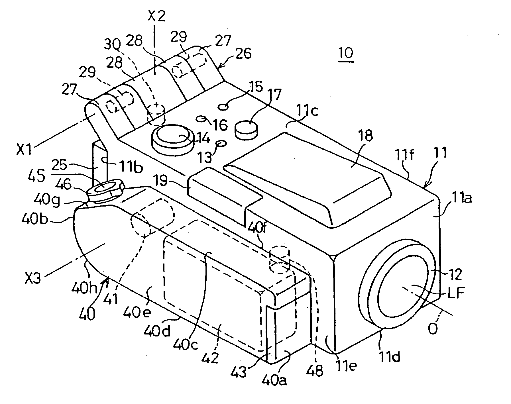
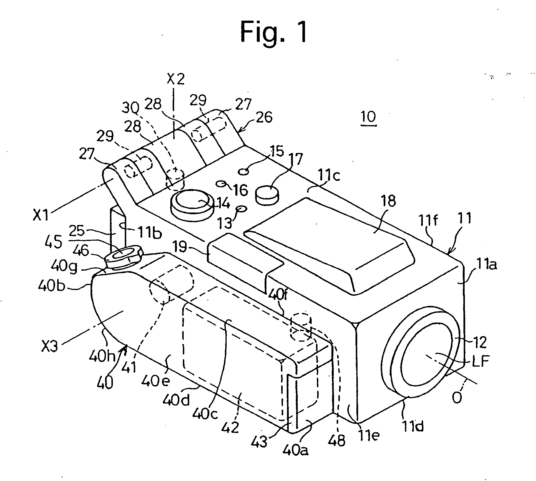
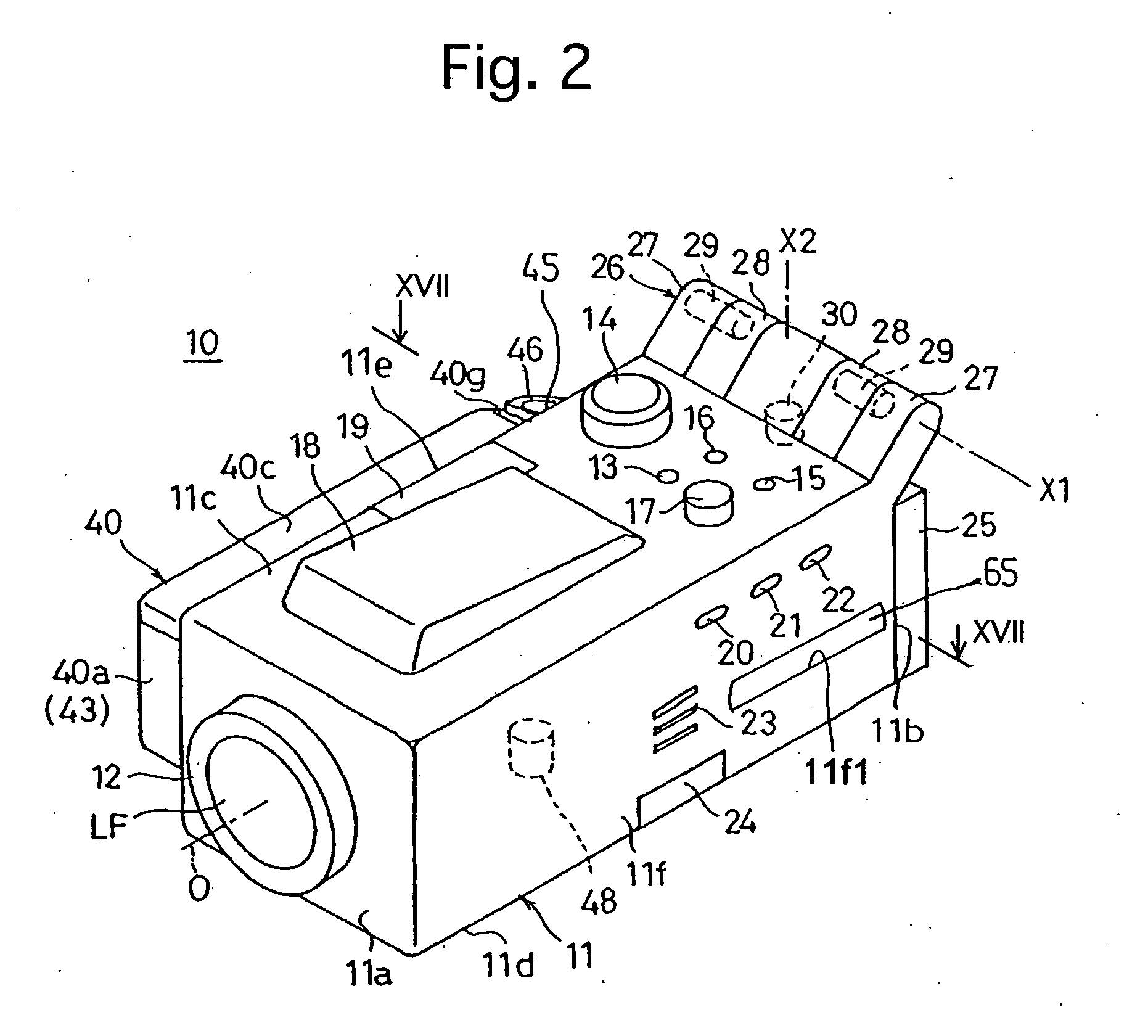
[0036]FIGS. 1 through 12 show an embodiment of a digital camera having a heat radiating structure according to the present invention. The digital camera 10 is provided with a camera body (outer casing) 11 including a photographing optical system (image-forming optical system) PY (see FIGS. 14 through 16). The camera body 11 is formed as a substantially rectangular parallelepiped which is elongated along an optical axis O of the photographing optical system PY. The outer surface of the camera body 11 is composed of six surfaces (flat portions): a front end surface 11a, a rear end surface 11b, a top surface 11c, a bottom surface 11d, a right side surface 11e, and a left side surface 11f. The top surface 11c, the bottom surface 11d, the right side surface 11e, and the left side surface 11f connect the front end surface 11a with the rear end surface 11b, and surround the optical axis O. In the present embodiment of the digital camera, the vertical direction and the horizontal direction ...


PUM

PropertyMeasurementUnit
range of rotationaaaaaaaaaa
angle of inclination K1aaaaaaaaaa

Abstract

A heat radiating structure of a digital camera includes an optical system holder which holds an image-forming optical system; an image pickup device supported by the optical system holder; an outer casing which constitutes an external body of the digital camera which surrounds the optical system holder, the outer casing having a through-hole which communicatively connects the inside of the outer casing with the outside thereof; an external radiating member installed in the through-hole, being made of a material having a thermal conductivity higher than that of the outer casing; a heat radiating plate, one end of which is connected to the image pickup device and another end of which extends into a space between the external radiating member and the optical system holder; and a heat transfer member via which the heat radiating plate and the external radiating member are connected to each other.

Description

BACKGROUND OF THE INVENTION [0001] 1. Field of the Invention [0002] The present invention relates to a heat radiating structure of a digital camera for cooling a solid-state image pickup device provided in the digital camera. [0003] 2. Description of the Related Art [0004] In conventional digital still / video cameras (hereinafter referred to simply as digital cameras), the heat generated by a solid-state image pickup device (e.g. a CCD or a CMOS image sensor) serving as an element of an imaging device needs to be dissipated with efficiency to prevent image data, which is output from the imaging device, from including noise caused by the heat generated by the solid-state image pickup device and to prevent the optical accuracy of an optical unit from deteriorating due to an expansion of the optical unit which is caused by the heat generated by the solid-state image pickup device. For instance, many digital cameras are provided with an LCD indicator on the back of the camera body, so th...

Claims


Application Information

Patent Timeline
Patent Type & Authority Applications(United States)
IPC IPC(8): G11B7/00H04N5/225H04N101/00
CPCH04N5/2252H04N23/51
Inventor KOSAKO, KOSEI
Owner ASAHI KOGAKU KOGYO KK
Learn More