CT image production method and X-ray CT system

a production method and image technology, applied in tomography, instruments, nuclear engineering, etc., can solve the problem of too long processing tim

Active Publication Date: 2005-11-17
GE MEDICAL SYST GLOBAL TECH CO LLC
View PDF9 Cites 0 Cited by
  • Summary
  • Abstract
  • Description
  • Claims
  • Application Information

AI Technical Summary

Benefits of technology

[0048] According to a CT image production method and an X-ray CT system in which the present invention is implemented, production of a large amount of data that is not actually used to construct a CT image can be avoided, and a common procedure can be adapted to rec

Problems solved by technology

However, since a large amount of data that is not actually used to construct

Method used


Image

  • CT image production method and X-ray CT system
  • CT image production method and X-ray CT system
  • CT image production method and X-ray CT system

Examples


first embodiment

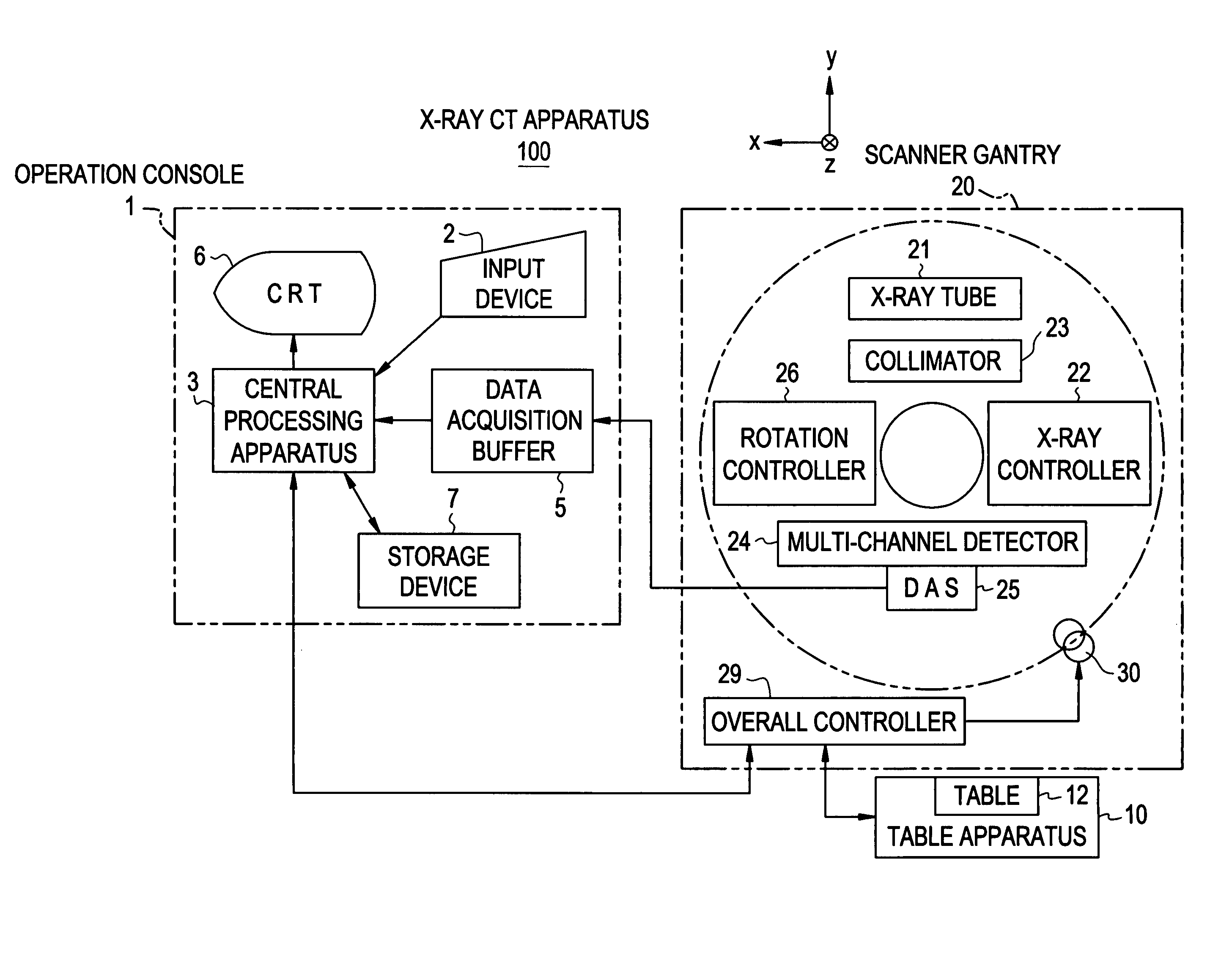
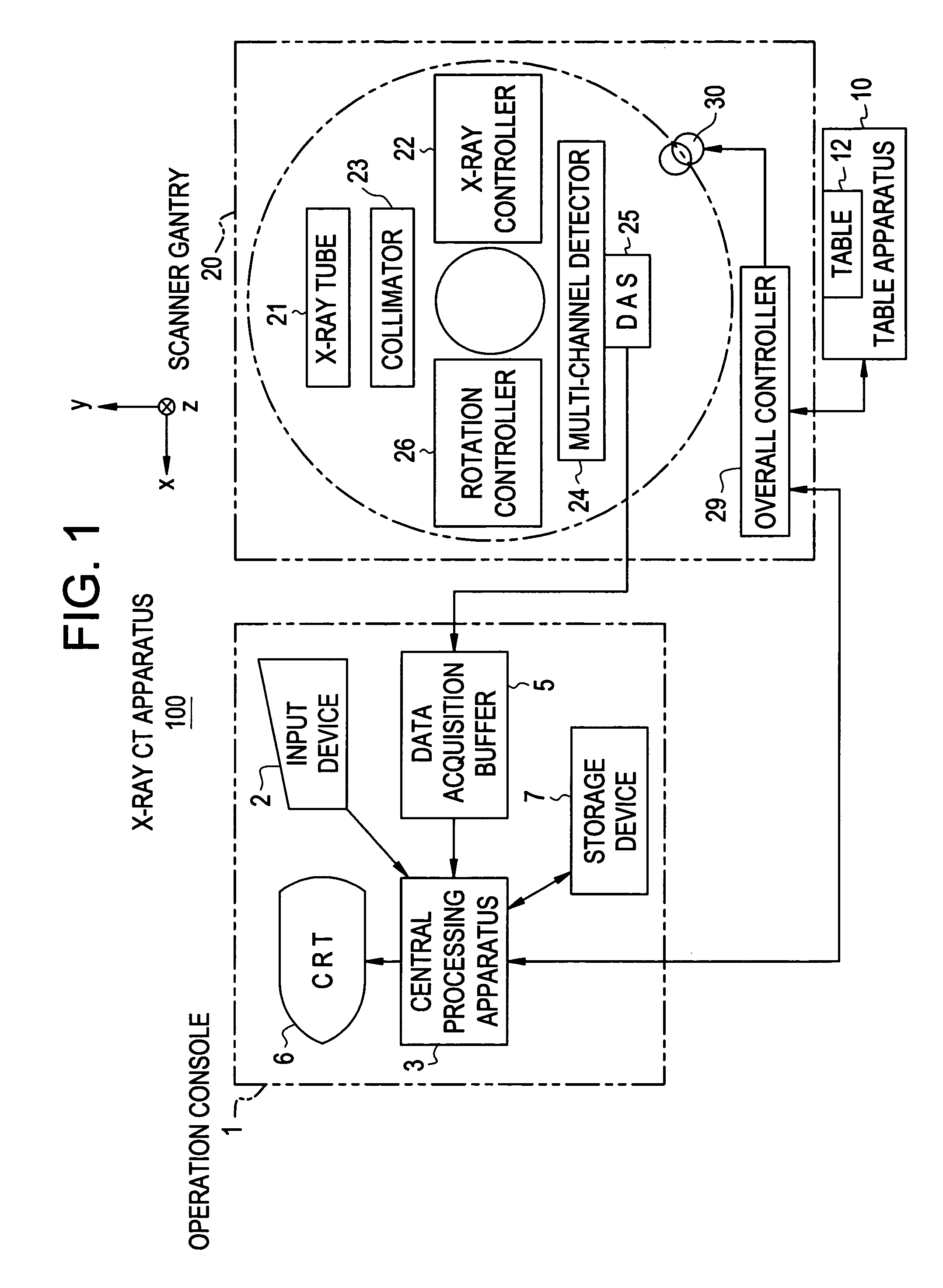
[0072]FIG. 1 is a block diagram showing the configuration of an X-ray CT system 100 in accordance with the first embodiment.

[0073] The X-ray CT system 100 comprises an operator console 1, a radiographic table assembly 10, a scanner gantry 20.

[0074] The operator console 1 comprises an input device 2 that receives an operator's entry, a central processing unit 3 that executes a scan control process or image reconstruction, a data collection buffer 5 in which data acquired by the scanner gantry 20 is recorded, a CRT 6 on which a reconstructed CT image is displayed, and a storage device 7 in which programs, data, and CT images are stored.

[0075] The radiographic table assembly 10 includes a radiographic table 12 on which an object of radiography lies down and which carries the object of radiography into or out of a bore of the scanner gantry 20. The radiographic table 12 is raised or lowered and rectilinearly moved by a motor incorporated in the radiographic table assembly 10.

[0076] ...

second embodiment

[0110]FIG. 16 is a flowchart describing CT image production in accordance with the second embodiment.

[0111] At step S1, the X-ray tube 21 and multi-channel detector 24 are moved to be opposed to each other at a desired position of scanning (in practice, the radiographic table 12 is rectilinearly moved).

[0112] At step S2, axial scanning or helical scanning is performed in order to acquire real data.

[0113] Herein, as shown in FIG. 17, the X-ray tube 21 and multi-channel detector 24 are moved so that when the view angle view is 0°, they will be opposed to each other at the reference position Z=Z0. Real data shall be acquired in this state. Moreover, a CT image shall be constructed by weighting and summating a first CT image that expresses a first reconstruction plane P1 located at a first position Z=Z1, and a second CT image that expresses a second reconstruction plane P2 located at a second position Z=Z2.

[0114] Referring back to FIG. 16, at step S3, the acquired real data is subje...

third embodiment

[0127]FIG. 18 is a flowchart illustrating CT image procedure in accordance with the third embodiment.

[0128] At step S1, the X-ray tube 21 and multi-channel detector 24 are moved to be opposed to each other at a desired position of scanning (in practice, the radiographic table 12 is rectilinearly moved).

[0129] At step S2, axial scanning or helical scanning is performed in order to acquire real data.

[0130] Herein, as shown in FIG. 19(a) and FIG. 19(b), the X-ray tube 21 and multi-channel detector 24 are moved so that when the view angle view is 0°, they will be opposed to each other at the reference position Z=Z0 or Z=Z3. Real data shall be acquired in this state. Consequently, if axial scanning is designated, it must be performed twice or more. Moreover, a CT image expressing a first reconstruction plane P1 located at a first position Z=Z1 shall be produced.

[0131] Referring back to FIG. 18, at step S3, the acquired real data is subjected to preprocessing (including offset correct...


PUM


Abstract

A method to make a common procedure adaptable to reconstruction planes whose positions relative to a multi-channel detector are different from one another. A reference procedure required for construction of a CT image based on reference linear data representing one line or a plurality of lines formed on a reference reconstruction plane is preserved. Real data associated with a first reconstruction plane different from the reference reconstruction plane is used to produce virtual reference linear data equivalent to the reference linear data. A CT image is reconstructed based on the virtual reference linear data using the reference procedure.

Description

BACKGROUND OF THE INVENTION [0001] The present invention relates to a computed tomography (CT) image production method and an X-ray CT system. More particularly, the present invention relates to a CT image production method and an X-ray CT system in which production of a large amount of data that is not actually used to construct a CT image can be avoided and a common procedure can be adapted to reconstruction planes whose positions relative to a multi-channel detector are different from one another. [0002] One of CT image production methods that have been known in the past is such that: real data that is acquired by detector arrays included in a multi-channel detector and that is contained in one of views required for reconstruction of an image is projected onto a projection plane, which is a virtual plane, in a direction of X-ray transmission, and then interpolated or extrapolated on the projection plane in order to produce high-density data; data representing lines formed on a re...

Claims


Application Information

Patent Timeline
IPC IPC(8): A61B6/03G06T11/00
CPCY10S378/901G06T11/005A61B6/03
Inventor HAGIWARA, AKIRA
Owner GE MEDICAL SYST GLOBAL TECH CO LLC
Why Eureka
Try Eureka