Methods, systems, and computer program products for imperceptibly embedding structured light patterns in projected color images for display on planar and non-planar surfaces

a technology of structured light patterns and color images, applied in the field of embedded structured light patterns in projected images, can solve the problems of reducing the utility of pilot training, simulators and flight simulation programs unsuitable for use in arbitrary environments, and unsuitable for different environments

Active Publication Date: 2005-11-17
THE UNIV OF NORTH CAROLINA AT CHAPEL HILL
View PDF30 Cites 88 Cited by
  • Summary
  • Abstract
  • Description
  • Claims
  • Application Information

AI Technical Summary

Benefits of technology

[0010] According to one aspect, the subject matter described herein includes a method for imperceptibly embedding structured light patterns in projected color images and for adapting the images for display on arbitrary surfaces. The method includes selecting an image exposure period for detecting embedded structured light patterns in a projected image. The image exposure period may be selected based on analysis of projector pixel polarities for different pixel intensities of a pixel color. In one example, the image exposure period is selected to be a time period during which pixels of a display are reliably on or off for a range of intensity values for a given color. Another criterion for selecting the image exposure period may be that the pixel polarities vary for different intensities of the color during the exposure period. For example, if a pixel is always off or always on for all intensities during an exposure period, the pixel polarity may be unsuitable for encoding binary images as the exposure period would only be capable of encoding one value, i.e., on or off.

Problems solved by technology

Requiring that the projector be specially calibrated to a particular display screen makes the projector and the flight simulation program unsuitable for use in arbitrary environments.
However, because immersive flight simulators are calibrated to their particular display screens, such simulators are unsuitable for use in different environments.
Accordingly, portable flight simulators are limited to display on standard two-dimensional LCD or CRT display screens, which greatly decreases their utility in training pilots.
However, if the user desires that the display span more than one wall, a portion of a wall and the ceiling or the floor, or any other non-planar surface, portions of the image may be distorted due to the points on which individual pixels are displayed being located at different distances from the projector.
Requiring projector customization for each display surface is impractical and undesirable in light of the number of potential variations in display surfaces.
However, one problem with using structured light in combination with projected user images is that the structured light patterns are not visually pleasing to users.
For example, a user who wants to view a projection of his or her email interface on one or more walls of the user's office will not want the email interface to be projected simultaneously with a visible striped pattern, as the pattern would impair viewing of the email interface.
However, one problem with using infrared structured light patterns is that an infrared projector is required.
Infrared projectors are more expensive than visible light projectors and are not universally available.
Requiring two projectors further increases the expense and decreases the reliability of the display system.
Another problem with using infrared projectors is that current infrared projectors are not capable of projecting dynamically changing patterns at speeds that are sufficiently fast for simultaneous depth extraction and display.
For example, if a pixel is always off or always on for all intensities during an exposure period, the pixel polarity may be unsuitable for encoding binary images as the exposure period would only be capable of encoding one value, i.e., on or off.

Method used


Image

  • Methods, systems, and computer program products for imperceptibly embedding structured light patterns in projected color images for display on planar and non-planar surfaces
  • Methods, systems, and computer program products for imperceptibly embedding structured light patterns in projected color images for display on planar and non-planar surfaces
  • Methods, systems, and computer program products for imperceptibly embedding structured light patterns in projected color images for display on planar and non-planar surfaces

Examples


Embodiment Construction

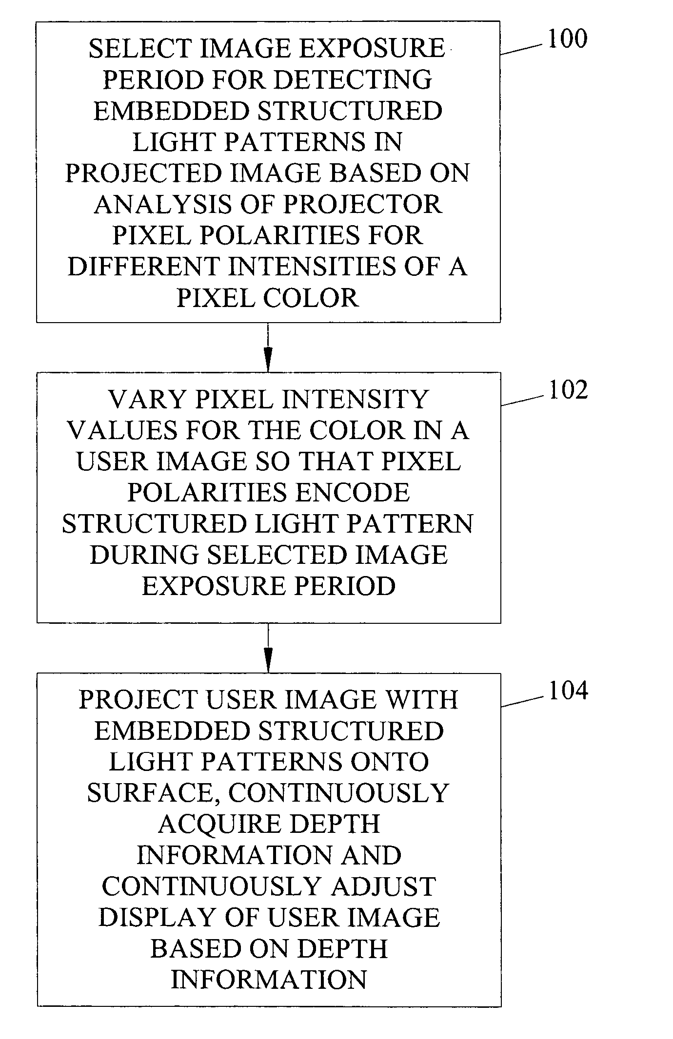
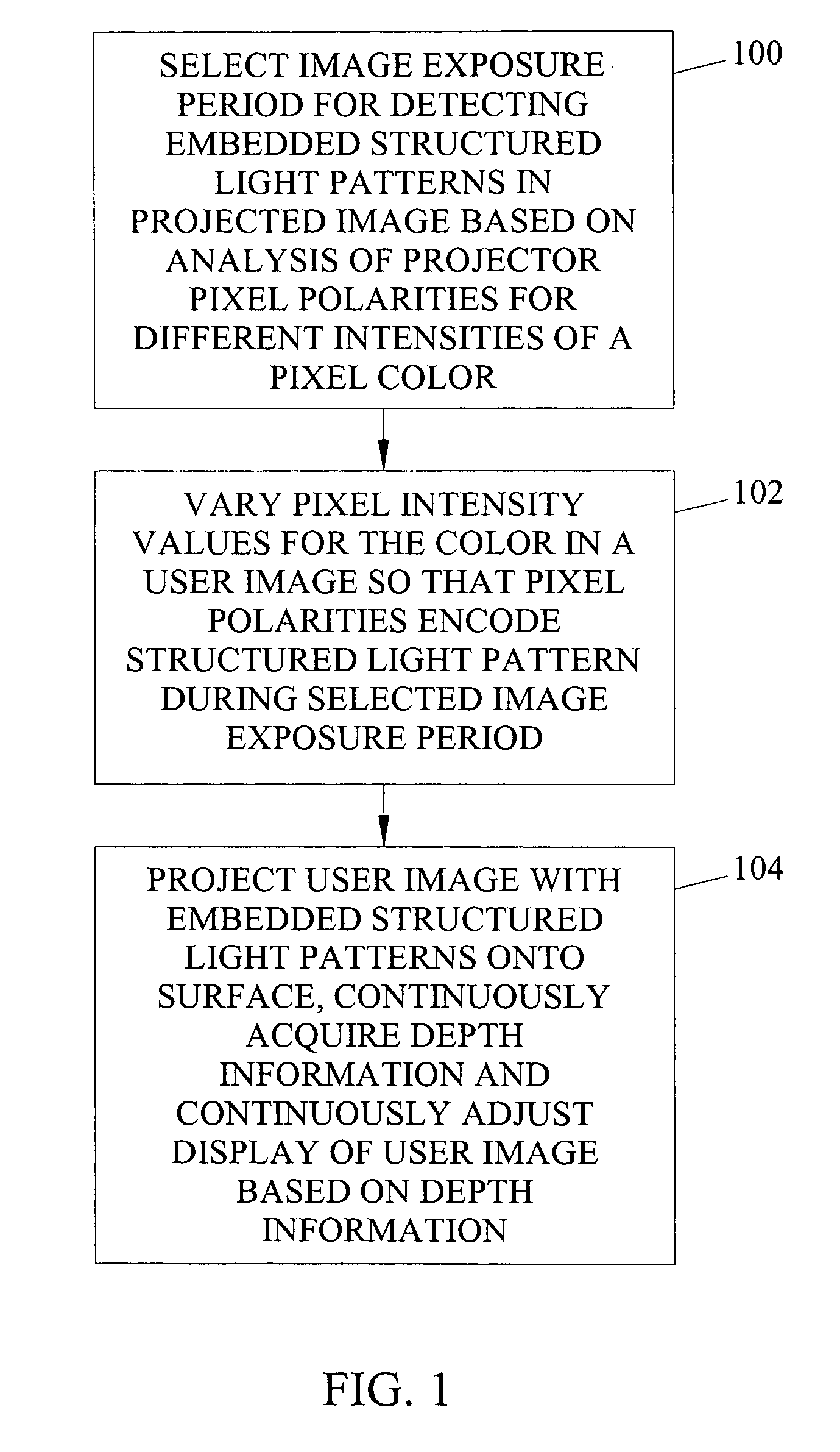
[0038] As described above, the subject matter described herein includes methods, systems, and computer program products for imperceptibly embedding structured light patterns in projected color images for display on planar and non-planar surfaces. FIG. 1 is a flow chart illustrating exemplary overall steps for embedding structured light patterns in a projected color image and for displaying the image on a surface using depth information obtained from the projection of the structured light patterns. Referring to FIG. 1, in step 100, an image exposure period is selected for detecting embedded structured light patterns in projected images based on analysis of projector pixel polarities for different pixel intensities of a pixel color. The image exposure period is the time during the display of each frame of a projected image that a camera will acquire the structured light pattern. The time is preferably selected such that a structured light pattern can be embedded in a user image withou...


PUM


Abstract

Methods, systems, and computer program products for imperceptibly embedding structured light patterns in projected color images for display on planar and non-planar surfaces are disclosed. According to one method, an image exposure period for detecting an embedded structured light patterns in a projected image is selected based on analysis of pixel polarities for different pixel intensities of a pixel color. Pixel intensities for the color are varied in the user image so that pixel polarities encode the structured light patterns during image exposure period. The user image is projected with the structured light patterns onto the surface. Depth information is continuously acquired and used to adjust display of the user image.

Description

RELATED APPLICATIONS [0001] This application claims the benefit of U.S. Provisional Patent Application Ser. No. 60 / 547,724, filed Feb. 25, 2004; the disclosure of which is incorporated herein by reference in its entirety.GOVERNMENT INTEREST [0002] This invention was made with U.S. Government support under grant number N00014-03-1-0589 awarded by the Defense Advanced Research Projects Agency (DARPA) through the Office of Naval Research (ONR) and undergrant number IIS-0121293 awarded by the National Science Foundation (NSF). The U.S. Government has certain rights in the invention.TECHNICAL FIELD [0003] The subject matter described herein relates to embedding structured light patterns in projected images, such as color images. More particularly, the subject matter described herein relates to methods, systems, and computer program products for imperceptibly embedding structured light patterns in projected color images for display on planar and non-planar surfaces. BACKGROUND ART [0004] ...

Claims


Application Information

Patent Timeline
Patent Type & Authority Applications(United States)
IPC IPC(8): G06K9/00G06K9/36H04N5/74H04N17/00
CPCH04N5/74H04N9/3194H04N9/3185H04N9/3182
Inventor FUCHS, HENRYCOTTING, DANIELNAEF, MARTINGROSS, MARKUS
Owner THE UNIV OF NORTH CAROLINA AT CHAPEL HILL
Why Eureka
Try Eureka