Torque rod and method of producing the same

a technology of torque rods and torque rods, which is applied in the direction of rod connections, jet propulsion mounting, transportation and packaging, etc., can solve the problems of high manufacturing cost, affecting the production efficiency of torque rods, and affecting the performance of torque rods, so as to reduce the weight and cost. the effect of low cos

Inactive Publication Date: 2005-11-17
SUMITOMO RIKO CO LTD
View PDF0 Cites 35 Cited by
  • Summary
  • Abstract
  • Description
  • Claims
  • Application Information

AI Technical Summary

Benefits of technology

[0014] It is an object of the present invention to provide a torque rod that maintains functionality comparable to the prior art but at lower cost, and that enables reduced weight.
[0024] According to the present invention, in addition to the fact per se that a metal sleeve is unnecessary, there is also no longer any need for a bonding process to bond the metal sleeve and the rubber elastic body together, a caulking process in order to constrict the diameter of the metal sleeve after vulcanization, or a cutting process performed on the inside circumferential face of the outer cylinder prior to press-fitting. Additionally, since there is no need to provide a protruding portion on the outside circumferential face of the inner cylinder so that the outside circumferential face of the inner cylinder can be a straight surface, the cost of producing the second bushing and of installation in the outer cylinder can be made lower, and thus the cost of the torque rod per se can be reduced. Since the metal sleeve can be dispensed with and the need to provide a protruding portion on the outside circumferential face of the inner cylinder is obviated so that its wall can be made thinner, the weight of the second bushing, and accordingly the weight of the torque rod, can be reduced so as to respond to the demand for lighter vehicle weight.
[0026] According to the third mode, the torque rod body is constituted as a molded component, and more particularly as a molded component of molding material injected in a fluid state into a forming mold and hardened, so that the torque rod body can be constituted as a molded component in this way. Therefore, an inwardly protruding shape like that mentioned above can be produced easily without subjecting the outer cylinder corresponding to the second bushing to a cutting process. Additionally, by employing this kind of inwardly protruding shape, it is possible to impart the draft angle required for demolding to the outer cylinder forming section of the torque rod forming mold.
[0029] According to the present invention, in order to eliminate a need for the metallic intermediate sleeve or other additional component, while achieving a required characteristics, i.e. an increased spring stiffness in the axis perpendicular direction, the present invention adopt a combination of the second outer cylinder of aforementioned unique configuration and the second bushing of aforementioned unique configuration. Namely, the second outer cylinder has the inside peripheral wall of inwardly protruding shape that becomes smaller in diameter moving towards the center from the axial ends. This unique configuration of the second outer cylinder makes is difficult to axially press-fit the second bushing into the bore of second outer cylinder, due to the presence of the central throttled portion. In order to make the press-fit process easy, if the second bushing is formed in the conventional round cylindrical configuration with a reduced wall thickness, a gap would be made at both axial end portions between the second outer cylinder and the rubber elastic body. To address this problem, if the second bushing is formed in the conventional round cylindrical configuration with a increased wall thickness, an axially central portion of the rubber elastic body is subjected to considerable stress, resulting in low durability of the second bushing.
[0030] To ensure a desired press-fitting of the second bushing to the second cylinder of unique configuration, the present rubber elastic body of the second bushing has the unique configuration as defined in the sixth mode. The presence of the central recessed portion makes it easy to insert the second bushing through the throttled portion of the second outer cylinder. The presence of the pair of side recessed portions makes it more easy to press fit the second bushing. Further, the side-recessed portion provides a large free surface of the rubber elastic body, enhancing durability of the second bushing. Additionally, the combination of the central recessed portion and the side-recessed portion makes it possible to closely fit the flange portions onto the end faces of the second outer cylinder, with high stability. Thus, the vibration-damping rod of construction according to the sixth mode of the invention ensures a further enhanced tightness between the second bushing and the second outer cylinder, preventing dislodging of the second bushing from the second outer cylinder.

Problems solved by technology

Such torque rods also damp vibration between the engine and body.
Consequently, a great number of steps are needed for manufacturing the torque rod 200, resulting in a problem of a high manufacturing cost.
These boost the manufacturing cost of the torque rods.

Method used


Image

  • Torque rod and method of producing the same
  • Torque rod and method of producing the same
  • Torque rod and method of producing the same

Examples


Embodiment Construction

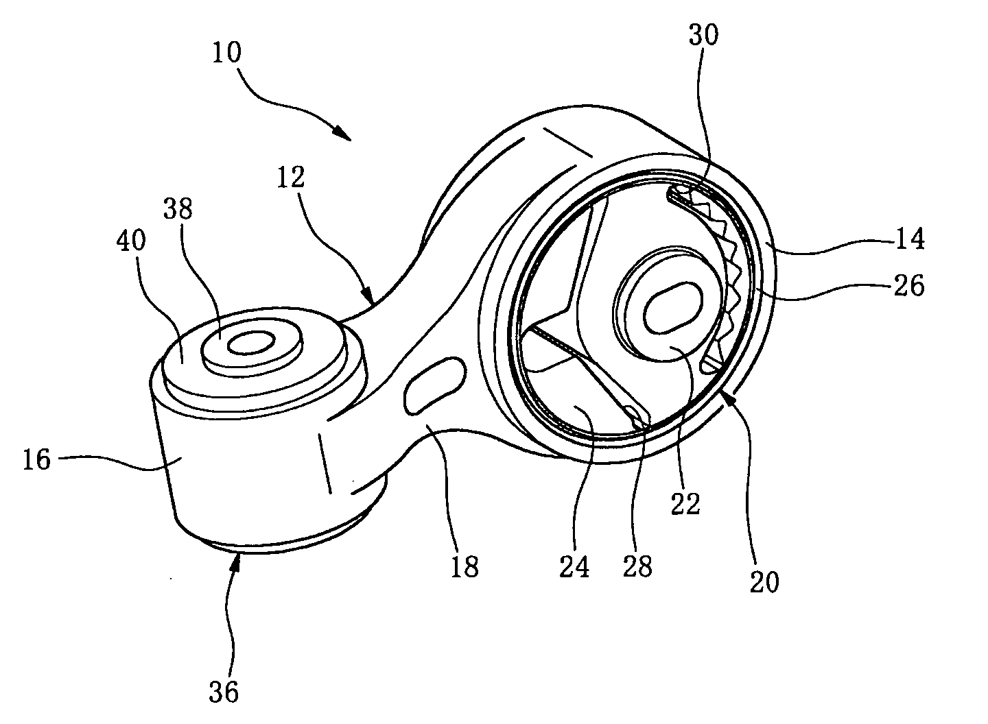
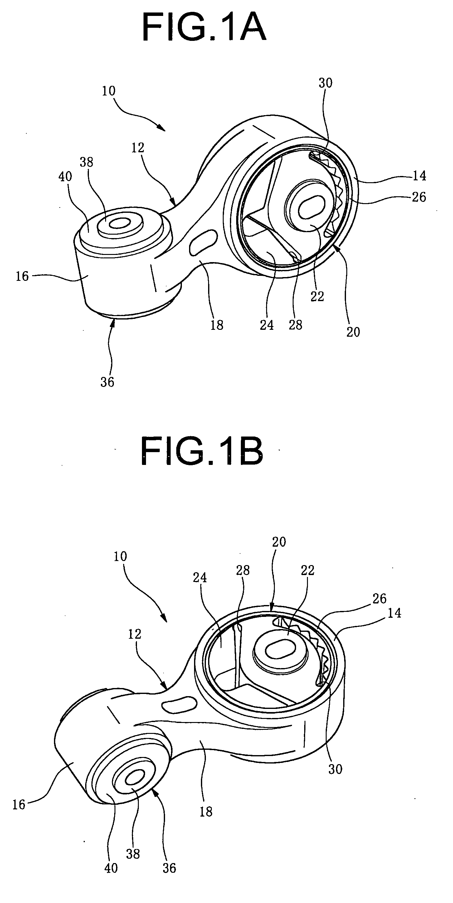
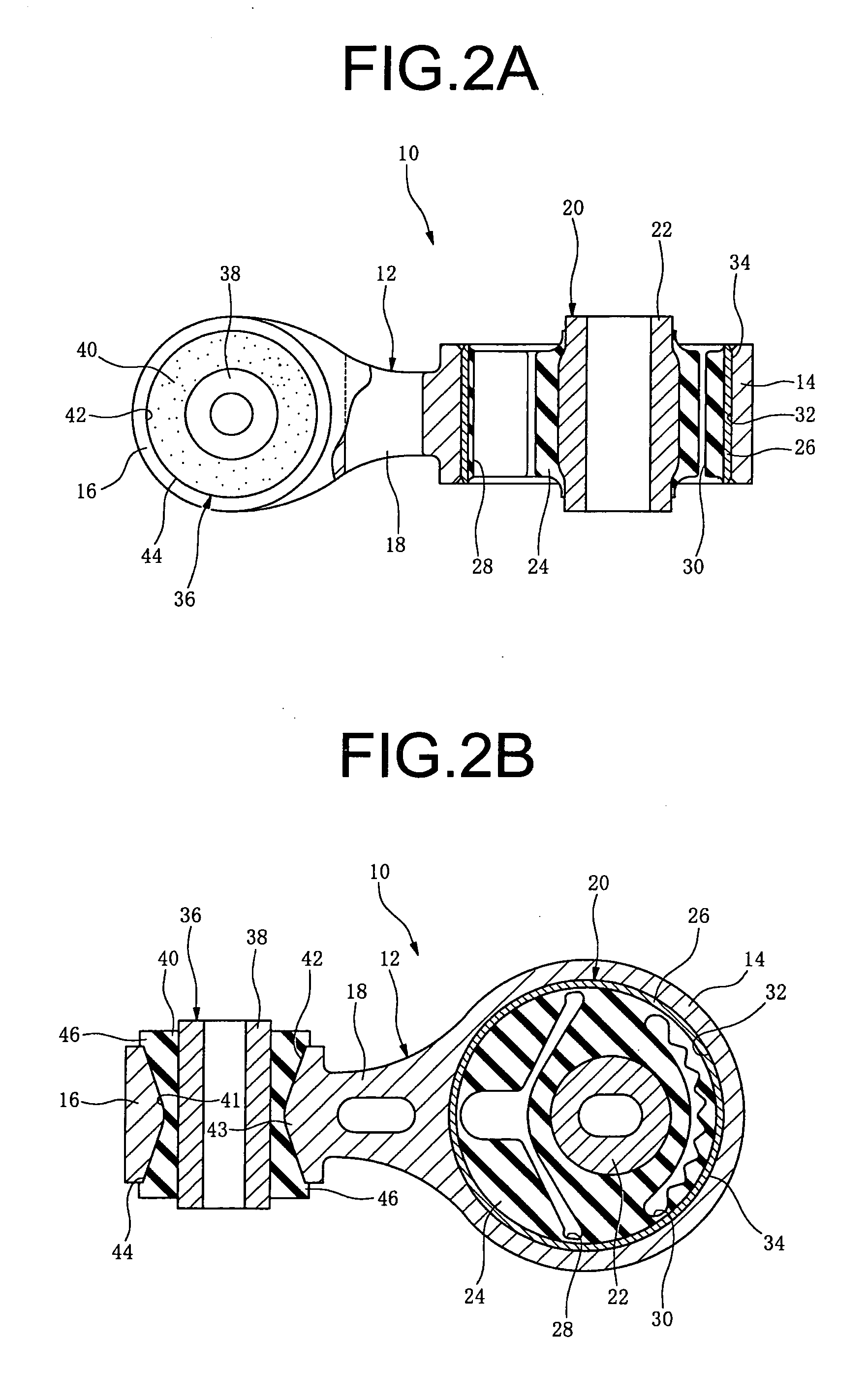
[0038] The embodiment of the invention is described in detail hereinbelow with reference to the drawings. In FIG. 1 and FIG. 2, 10 denotes a torque rod of construction according to the present embodiment, and 12 denotes a torque rod body fabricated of aluminum alloy (e.g., die-cast aluminum). The torque rod body 12 has at a first end thereof a first outer cylinder 14 of large-diameter round cylindrical shape, and at the other end thereof a small-diameter second outer cylinder 16 oriented in a direction forming a right angle therewith, with these being linked together by a linking portion 18.

[0039]20 denotes a first bushing consisting of a large bushing installed within the large-diameter first outer cylinder 14; it comprises a metal rigid inner cylinder 22, a rubber elastic body 24 attached thereabout, and a round cylindrical metal sleeve 26 attached to the outer circumferential face thereof. The rubber elastic body 24 is integrally bonded by vulcanization to the inner cylinder 22 ...


PUM


Abstract

A torque rod having: a rigid torque rod body of a form in which first and second outer cylinders at both ends are linked to each other by a linking portion; and a first and a second bushing each having a rigid inner cylinder and a rubber elastic body affixed thereabout, the first and second bushings being respectively installed within first and second outer cylinders. The second outer cylinder has an inside peripheral wall of inwardly protruding shape that becomes smaller in diameter moving towards the center from the axial ends. The rubber elastic body of the second bushing is a solid member having a shape corresponding to the inwardly protruding shape, with the second bushing installed directly press-fit in the axial direction into the second outer cylinder, at an outer circumferential face of the rubber elastic body.

Description

INCORPORATED BY REFERENCE [0001] The disclosure of Japanese Patent Application No. 2004-132532 filed on Apr. 28, 2004 including the specification, drawings and abstract is incorporated herein by reference in its entirety. BACKGROUND OF THE INVENTION [0002] 1. Field of the Invention [0003] The present invention relates to a torque rod that is interposed between the engine and body of a vehicle to control displacement of the engine in the engine rolling direction and the vehicle front-back direction, as well as to damp vibration between the engine and body. [0004] 2. Description of the Related Art [0005] Conventionally, torque rods are mounted between the engine and body of a vehicle. These torque rods have first and second bushings at both ends, each of which has an outer and inner cylinder, with a rubber elastic body interposed therebetween, and a linking portion for connecting the first and second bushings, so that the torque rods can take up the torque from the engine to control d...

Claims


Application Information

Patent Timeline
Patent Type & Authority Applications(United States)
IPC IPC(8): F16F15/08B60K5/12F16B7/08F16F1/38
CPCB60K5/1208Y10T403/39F16F1/3849
Inventor OJI, AKIRA
Owner SUMITOMO RIKO CO LTD
Why Eureka
Try Eureka