Methods of inserting conically-shaped fusion cages

a fusion cage and conical shape technology, applied in the field of fusion of adjacent vertebral bodies or bone structures, can solve the problems of affecting the fusion cage self-tapping nature and the inability of the disk material to support the threads, and achieve the effect of accurately positioning and enhancing the self-tapping nature of the fusion cag

Inactive Publication Date: 2005-11-17
HOWMEDICA OSTEONICS CORP
View PDF8 Cites 9 Cited by
  • Summary
  • Abstract
  • Description
  • Claims
  • Application Information

AI Technical Summary

Benefits of technology

[0007] In a second embodiment of the present invention, a fusion cage includes a conically-shaped cage body having a proximal end and a distal end with the distal end having a diameter which is smaller than the diameter of the proximal end. The conically-shaped cage body has a conically-shaped outer surface and at least one flute formed in the conically-shaped outer surface. The flute acts as a relief much as the flute placed on self-tapping screws in order to facilitate the insertion of the fusion cage using a twisting motion between two vertebral bone structures.
[0010] In another aspect of the invention which can be included in any of the above embodiments, the cage body can have a round or bull nose distal end with one or more flutes formed in the round or bull nose distal end in order to enhance the self-tapping nature of the fusion cage.
[0011] In yet another aspect of the invention, introduction tools allow the fusion cage to be accurately positioned between the vertebral bone structures.

Problems solved by technology

Without two or more flutes, wandering might occur due to the fact that the threads are only substantially engaged with the vertebral bone structures and not with the disk material between the vertebral bone structures, which disk material does not provide support to the threads.

Method used


Image

  • Methods of inserting conically-shaped fusion cages
  • Methods of inserting conically-shaped fusion cages
  • Methods of inserting conically-shaped fusion cages

Examples


Embodiment Construction

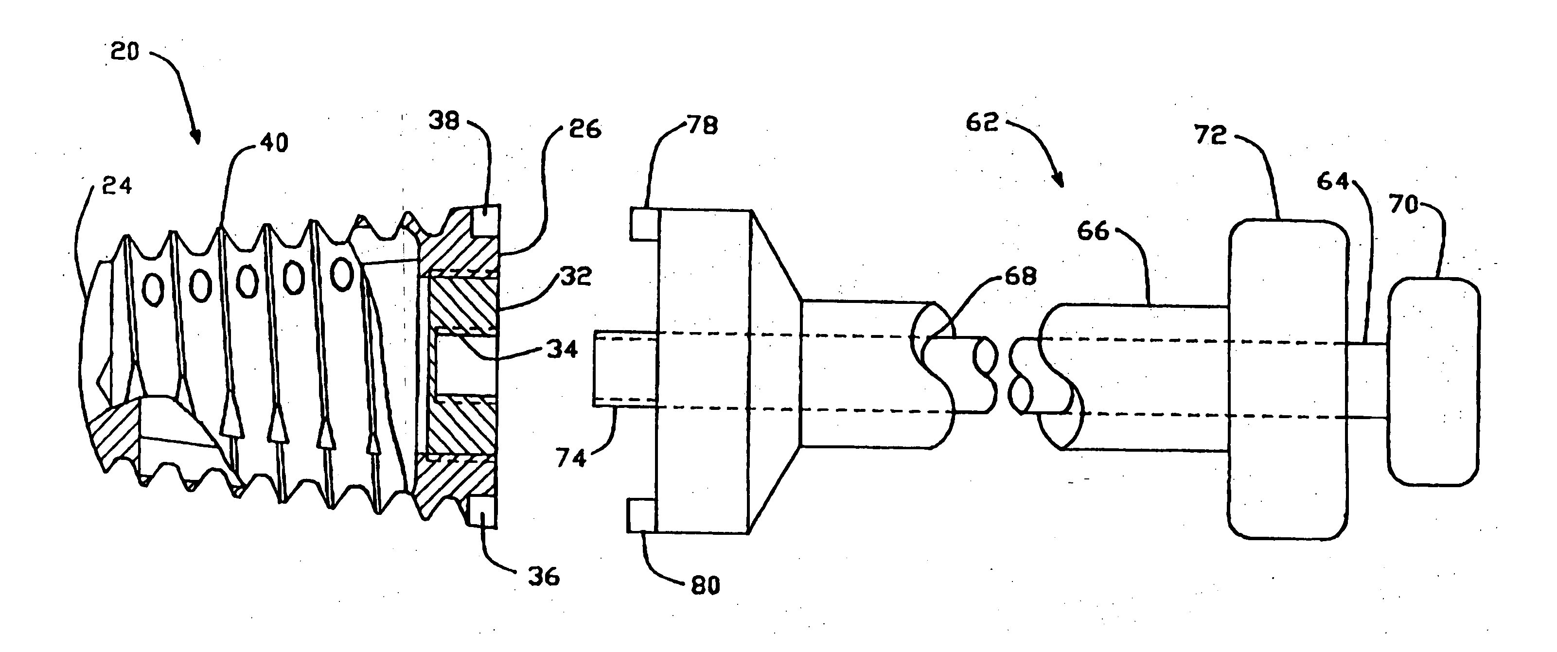
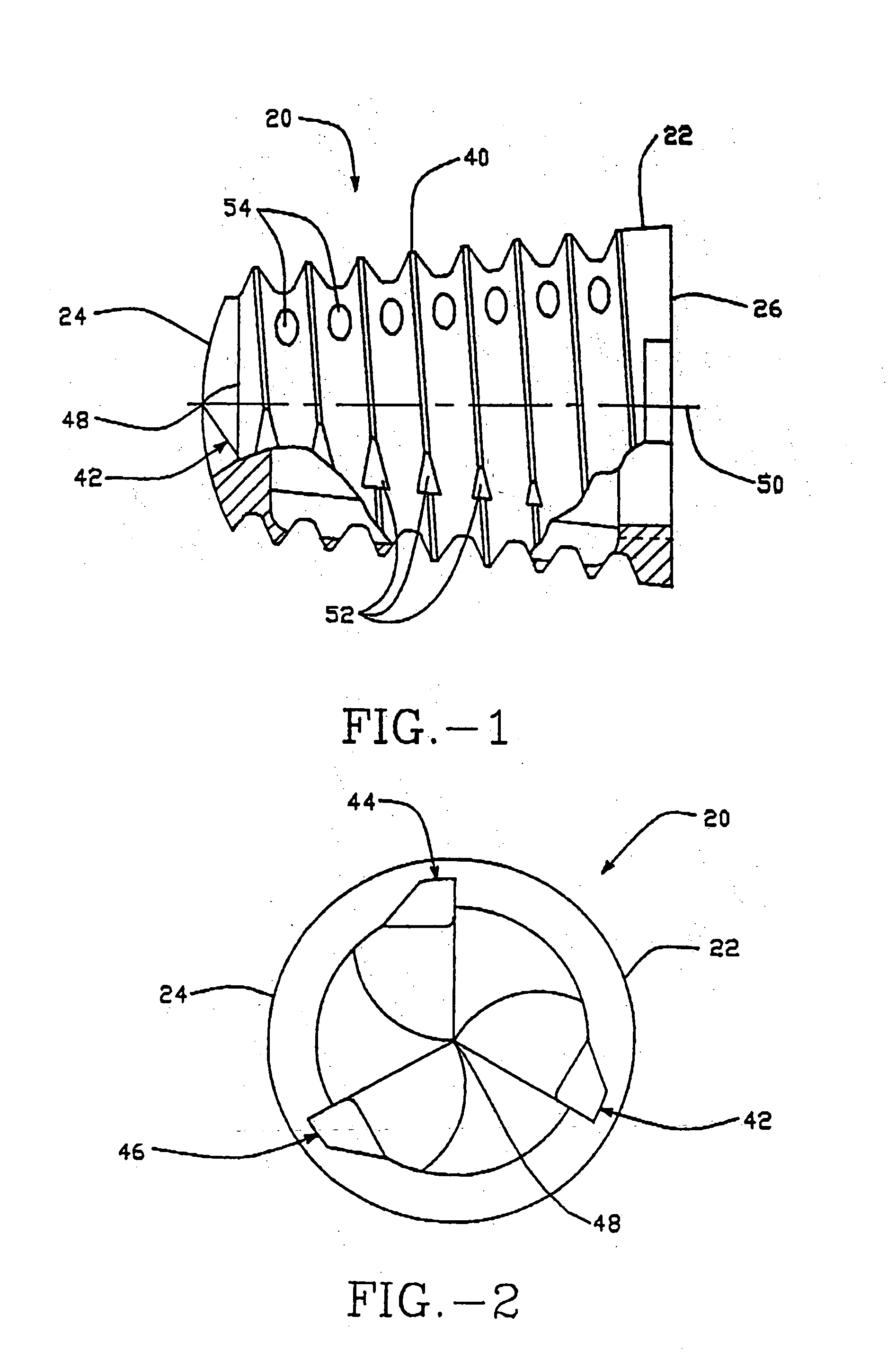
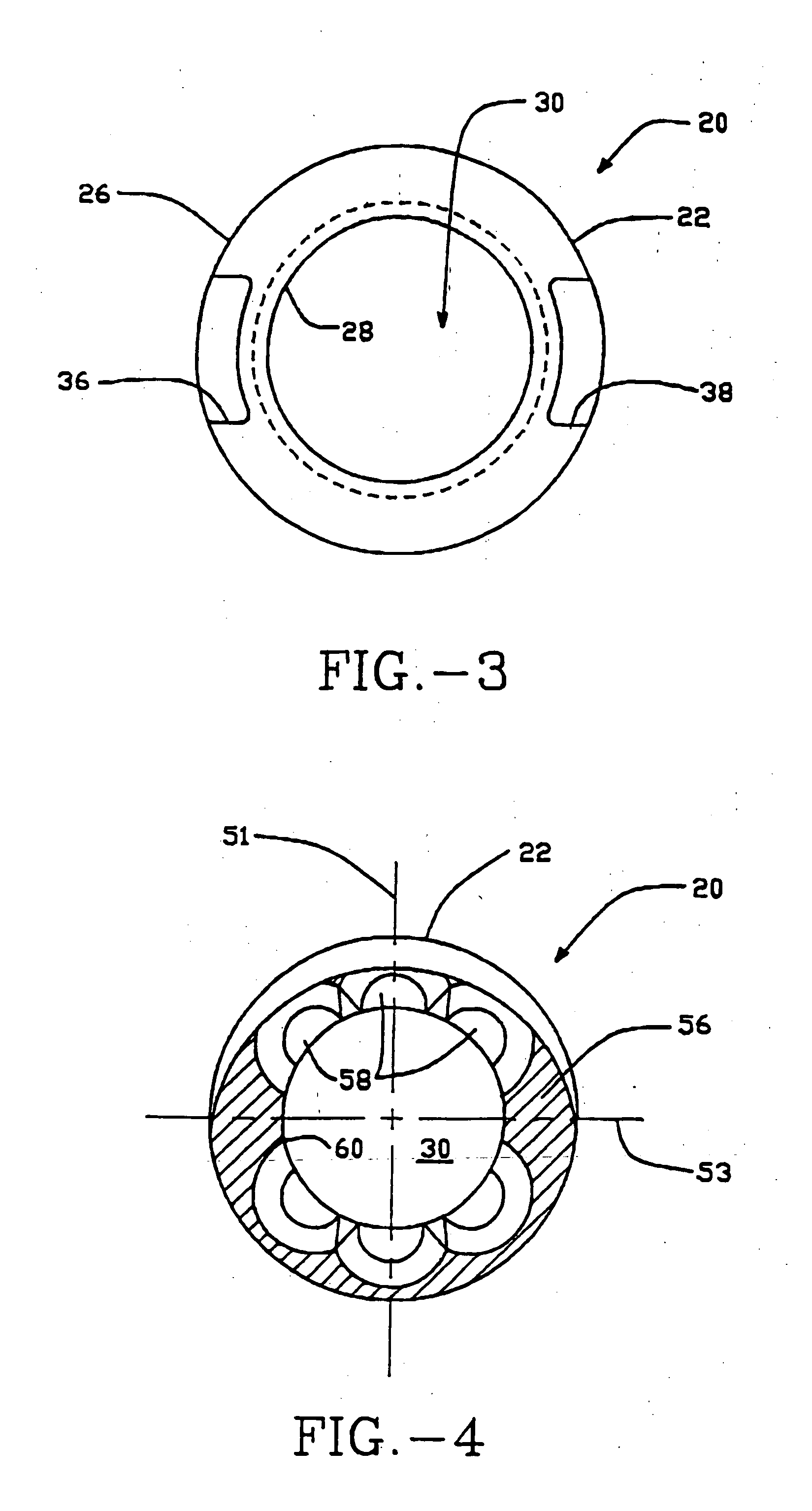
[0030] With respect to the figures in a particular FIG. 1, a side view of the preferred embodiment of the fusion cage 20 is depicted. Fusion cage 20 includes a fusion cage body 22 which in this preferred embodiment is provided in the shape of a cone. Fusion cage 20 includes a distal end 24 and a proximal end 26. The distal end 24 in a preferred embodiment is rounded or bull nosed in order to facilitate the insertion of the fusion cage 20 relative to one or more bone structures. The proximal end 26 includes an opening 28 which communicates with an internal cavity 30 defined by the fusion cage 20. The opening 28 in a preferred embodiment is threaded so that it can receive an end cap or plug 32 (FIG. 5). End cap 32 is used to close off the proximal end 26 and retain bone growth inducing substances packed therein as described hereinbelow. As can be seen in FIG. 5, end cap 32 includes a threaded bore 34 which is designed to receive an insertion tool. The threaded bore 34 has an initial u...


PUM


Abstract

A method of promoting fusion of adjacent vertebral bodies include providing a conically-shaped cage body having bone engaging projections on an outer surface thereof, the cage body including a leading end having a first diameter and a trailing end having a second diameter that is larger than the first diameter. The method also includes positioning the leading end of the cage body adjacent an intervertebral disc space between an upper vertebral body and a lower vertebral body, whereby the upper and lower vertebral bodies have opposing end faces that define upper and lower limits of the intervertebral disc space. While urging the leading end of the cage body into the intervertebral disc space, the cage body is turned so that the bone engaging projections bite into the opposing end faces of the upper and lower vertebral bodies for anchoring the cage body to the upper and lower vertebral bodies.

Description

CROSS REFERENCE TO RELATED APPLICATIONS [0001] The present invention is a continuation of U.S. patent application Ser. No. 10 / 350,834, filed Jan. 24, 2003, which is a continuation of U.S. patent application Ser. No. 09 / 358,188, filed Jul. 20, 1999, abandoned, which is a continuation of U.S. patent application Ser. No. 08 / 781,525, filed Jan. 9, 1997, abandoned, which is a file wrapper continuation of U.S. patent application Ser. No. 08 / 306,879 filed Dec. 15, 1994, abandoned. The disclosures of the '834, '188, '525 and '879 applications are hereby incorporated by reference herein.BACKGROUND OF THE INVENTION [0002] This invention is directed to devices and methods for facilitating the fusing of bone structures and more particularly the fusing together of adjacent vertebral bodies or bone structures. [0003] Technical literature and patent documents disclose a number of devices and methods for fusing bones together. One such device which has proven to be successful is disclosed in U.S. P...

Claims


Application Information

Patent Timeline
Patent Type & Authority Applications(United States)
IPC IPC(8): A61F2/28A61B17/56A61B17/58A61B17/70A61B17/86A61B17/88A61F2/00A61F2/30A61F2/44A61F2/46
CPCA61B17/862A61F2310/00023A61F2/30744A61F2/442A61F2/446A61F2/4601A61F2/4611A61F2/4637A61F2002/2835A61F2002/30121A61F2002/30143A61F2002/30154A61F2002/3021A61F2002/30217A61F2002/30235A61F2002/30327A61F2002/30382A61F2002/30405A61F2002/30617A61F2002/30774A61F2002/30777A61F2002/30785A61F2002/30787A61F2002/30797A61F2002/30813A61F2002/3082A61F2002/3085A61F2002/30863A61F2002/30874A61F2002/30968A61F2002/4475A61F2002/448A61F2002/4623A61F2002/4624A61F2002/4627A61F2002/464A61F2220/0025A61F2220/0033A61F2230/0006A61F2230/0017A61F2230/0021A61F2230/0067A61F2230/0069A61F2250/0039A61F2250/0097A61B17/8883A61F2/4603A61F2002/30331A61F2002/30593A61F2002/30873
Inventor PAVLOV, PAUL W.WINSLOW, CHARLES J.JAYNE, KIRKKLYCE, HENRY A.
Owner HOWMEDICA OSTEONICS CORP
Why Eureka
Try Eureka