Node processors for use in parity check decoders

a parity check and decoder technology, applied in the field of node processors for use in parity check decoders, can solve the problems of implementing the algorithm that affects the function f and its inverse, and achieves the effect of reducing the complexity of the implementation

Inactive Publication Date: 2005-11-17
QUALCOMM INC
View PDF60 Cites 51 Cited by
  • Summary
  • Abstract
  • Description
  • Claims
  • Application Information

AI Technical Summary

Benefits of technology

[0045] Note that if we choose δ=ln2 then the computation required for the check node reliability update is particularly simple, allowing for an implementation using addition and shift operations. It turns out, for code rates above roughly ⅕, that setting δ=ln2 provides sufficient resolution to achieve nearly full belief propagation performance. For lower rates this quantization is too coarse and setting δ=½ ln2 can be preferable. The main advantage of choosing δ in this way is that it greatly simplifies calculation of the ln operation.

Problems solved by technology

It is evident, according to our description, that the main difficulty encountered in implementing the algorithm concerns the function F and its inverse.

Method used


Image

  • Node processors for use in parity check decoders
  • Node processors for use in parity check decoders
  • Node processors for use in parity check decoders

Examples


Embodiment Construction

[0049] As discussed above, the decoding methods and apparatus of the present invention will be described, for purposes of explanation, in the context of an LDPC decoder embodiment. Steps involved in decoding of an LDPC code will first be described with reference to FIGS. 4 and 5 followed by a more detailed discussion of the present invention.

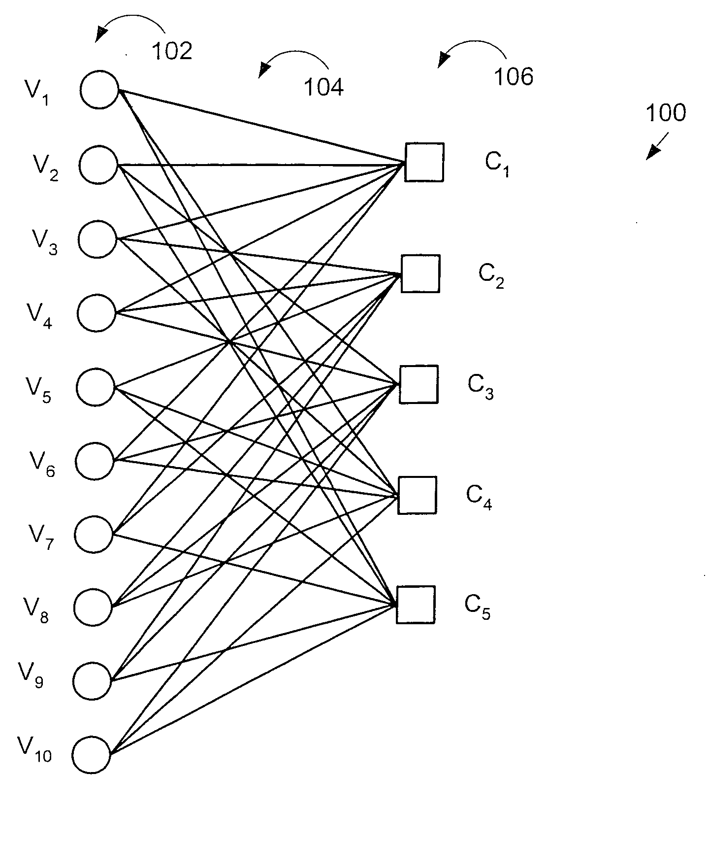
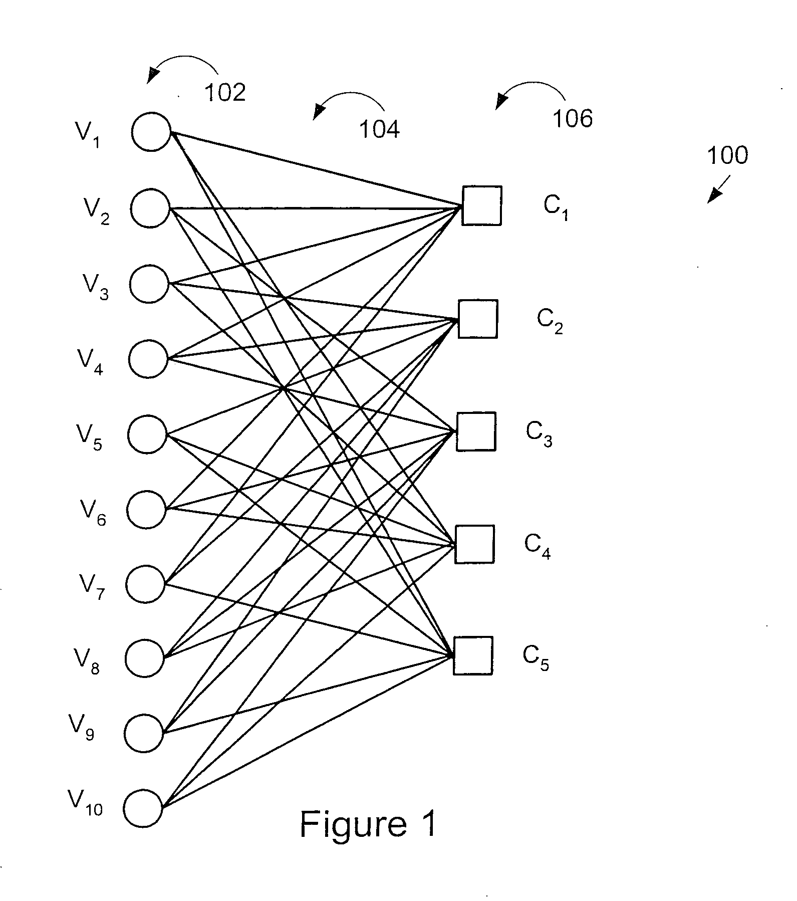
[0050]FIG. 4 illustrates an exemplary irregular LDPC code using a bipartite graph 400. The graph includes m check nodes 402, n variable nodes 406, and a plurality of edges 404. Messages between the check nodes and variable nodes are exchanged over the edges 404. Soft input bits yl through yn, corresponding to the received word Y, and soft (or hard) outputs xi through xn are indicted by reference numeral 408. The mth check node is identified using reference numeral 402′, the nth variable node is identified using reference numeral 406′ while the nth soft input yn and the nth soft output xn are indicated in FIG. 4 using reference numbers 410, 409 ...


PUM


Abstract

Techniques for implementing message passing decoders, e.g., LDPC decoders, are described. To facilitate hardware implementation messages are quantized to integer multiples of ½ ln2. Messages are transformed between more compact variable and less compact constraint node message representation formats. The variable node message format allows variable node message operations to be performed through simple additions and subtractions while the constraint node representation allows constraint node message processing to be performed through simple additions and subtractions. Variable and constraint nodes are implemented using an accumulator module, subtractor module and delay pipeline. The accumulator module generates an accumulated message sum. The accumulated message sum for a node is stored and then delayed input messages from the delay pipeline are subtracted there from to generate output messages. The delay pipeline includes a variable delay element making it possible to sequentially perform processing operations corresponding to nodes of different degrees.

Description

RELATED APPLICATIONS [0001] This application claims the benefit of U.S. Provisional Application Ser. No. 60 / 328,469 filed Oct. 10, 2001 and the benefit of U.S. Provisional Application Ser. No. 60 / 298,480 filed Jun. 15, 2001 and is a continuation-in-part of U.S. patent application Ser. No. 09 / 975,331 filed Oct. 10, 2001 each of which is hereby expressly incorporated by reference.FIELD OF THE INVENTION [0002] The present invention is directed to methods and apparatus for detecting and / or correcting errors in binary data, e.g., through the use of parity check codes such as low density parity check (LDPC) codes. BACKGROUND [0003] Error correcting codes are ubiquitous in communications and data storage systems. Recently a considerable interest has grown in a class of codes known as low-density parity-check (LDPC) codes. [0004] LDPC codes are well represented by bipartite graphs, often called Tanner graphs, in which one set of nodes, the variable nodes, corresponds to bits of the codeword...

Claims


Application Information

Patent Timeline
Patent Type & Authority Applications(United States)
IPC IPC(8): G06F17/50G06N3/02H03M13/03H03M13/11
CPCG06N3/02H03M13/1125H03M13/1111H03M13/1117H03M13/112H03M13/1131H03M13/1134H03M13/1137H03M13/114H03M13/1145H03M13/6362H03M13/6502H03M13/6577H03M13/658H03M13/1102
Inventor RICHARDSON, TOMNOVICHKOV, VLADIMIR
Owner QUALCOMM INC
Why Eureka
Try Eureka