Moment frame links wall

Active Publication Date: 2005-11-24
SIMPSON STRONG TIE
View PDF50 Cites 64 Cited by
  • Summary
  • Abstract
  • Description
  • Claims
  • Application Information

AI Technical Summary

Benefits of technology

[0010] It is, therefore, an advantage of the present invention to provide a lateral bracing structure having high initial stiffness.
[0011] It is another advantage of the present invention to provide a lateral bracing system including controlled and predictable deflection and load bearing characteristics of the wall member and controlled and predictable yield of the yield links.
[0012] It is a still further advantage of the present invention to provide a lateral bracing system where failure is limited to the yield links, which are easily replaced, thereby restoring the lateral bracing system to its full load bearing capacity.
[0013] It is another advantage of the present invention to provide a lateral bracing system capable of fitting between conventionally located wall studs, and which can be isolated from gravity loads.
[0014] These and other advantages are provided by the present invention, which in embodiments relates to a lateral bracing system for use in constructions such as light framed constructions. The lateral bracing includes a structural moment frame supported between an underlying support surface suc

Problems solved by technology

Shear stresses due to natural phenomena such as seismic activity and high winds can have devastating effects on the structural integrity of light-framed constructions.
Lateral forces generated during such natural phenomena may cause the top portion of a wall to move laterally with respect to the bottom portion of the wall, which movement can result in damage or structural failure of the wall and, in some instances, collapse of the building.
Many conventional lateral bracing systems perform well initially under

Method used


Image

  • Moment frame links wall
  • Moment frame links wall
  • Moment frame links wall

Examples


Embodiment Construction

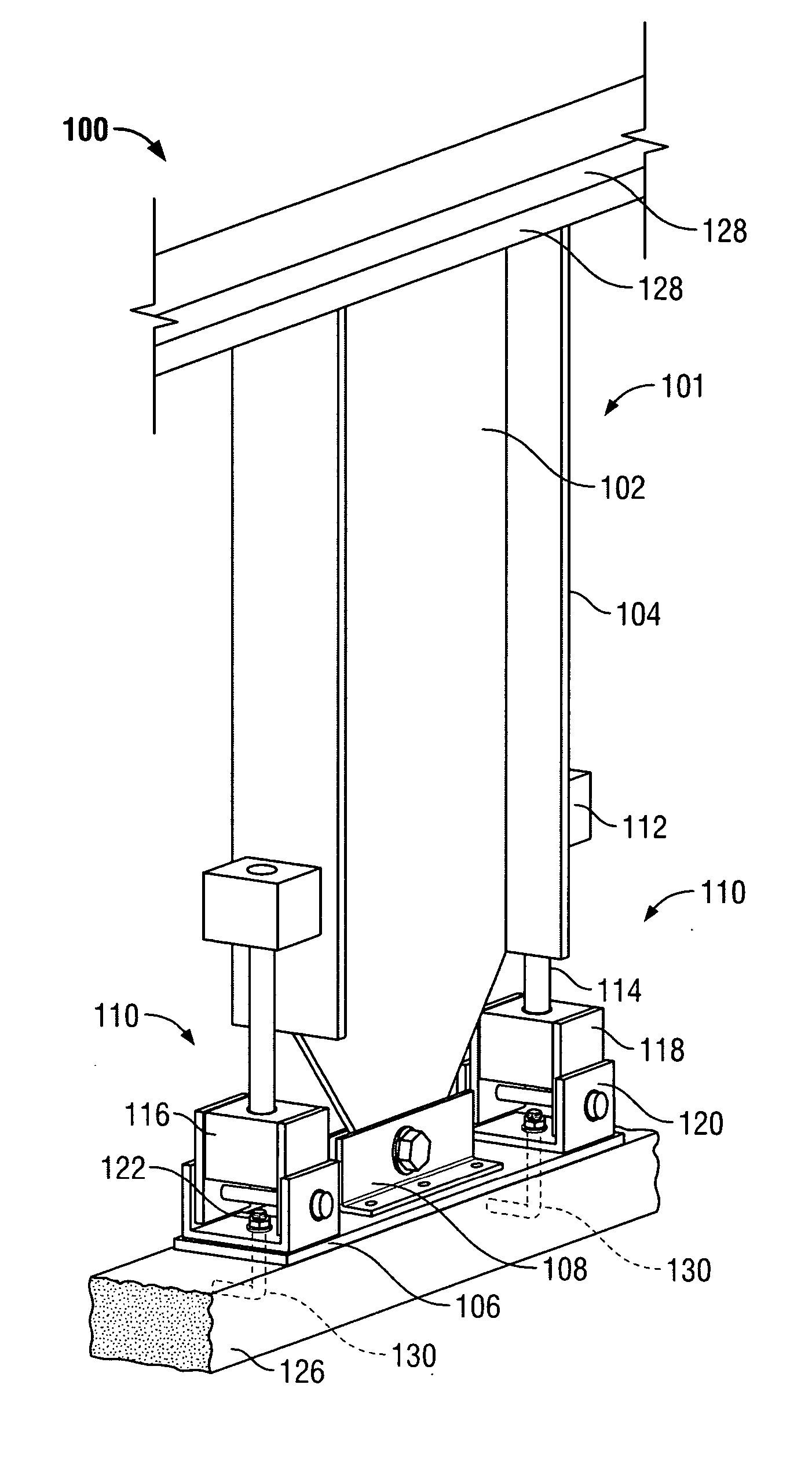
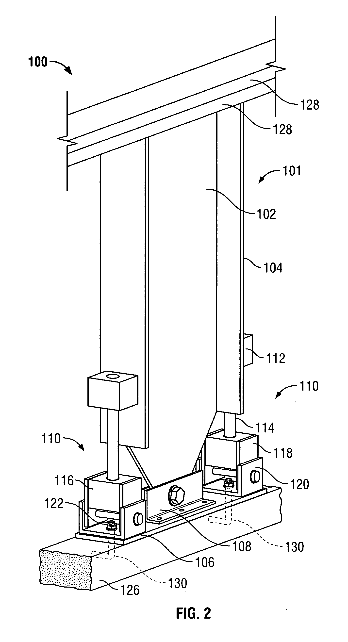
[0035] The present invention will now be described with reference to FIGS. 2 through 15, which in embodiments of the invention relate to a lateral bracing system having high initial stiffness and including yield links capable of effectively dissipating shear stresses generated within the lateral bracing system under lateral loads. It is understood that the present invention may be embodied in many different forms and should not be construed as being limited to the embodiments set forth herein. Rather these embodiments are provided so that this disclosure will be thorough and complete and will fully convey the invention to those skilled in the art. Indeed, the invention is intended to cover alternatives, modifications and equivalents of these embodiments, which are included within the scope and spirit of the invention as defined by the appended claims. Furthermore, in the following detailed description of the present invention, numerous specific details are set forth in order to prov...


PUM


Abstract

A lateral bracing system having high initial stiffness and including yield links capable of effectively dissipating stresses generated within the lateral bracing system under lateral loads.

Description

BACKGROUND OF THE INVENTION [0001] 1. Field of the Invention [0002] The present invention relates to hysteretic damping for structures used in light-framed constructions, and in particular to a lateral bracing system constructed to provide a high degree of energy dissipation through hysteretic damping along with high initial stiffness so that energy is dissipated at low force thresholds within a light-framed construction. [0003] 2. Description of the Related Art [0004] Shear stresses due to natural phenomena such as seismic activity and high winds can have devastating effects on the structural integrity of light-framed constructions. Lateral forces generated during such natural phenomena may cause the top portion of a wall to move laterally with respect to the bottom portion of the wall, which movement can result in damage or structural failure of the wall and, in some instances, collapse of the building. [0005] In constructions such as residences and small buildings, lateral bracin...

Claims


Application Information

Patent Timeline
IPC IPC(8): E04B1/24E04B1/98E04H9/02E04H9/14
CPCE04B1/2403E04B2001/2415E04B2001/2442E04B2001/2448E04H9/021E04B2001/2496E04H9/028E04H9/14E04B2001/2463E04H9/0237Y02A50/00E04B1/36E04B1/98E04B2/56
Inventor PRYOR, STEVEN E.ANDERSON, GUY T.
Owner SIMPSON STRONG TIE
Why Eureka
Try Eureka