Shear wall composed of multilayer steel plates

A technology of combining shear walls and multi-layer steel plates, which can be applied to walls, building components, earthquake resistance, etc., and can solve the problems of poor economic benefits, large steel consumption, and low shear buckling load.

Inactive Publication Date: 2012-02-08
WUXI RES INST OF APPLIED TECH TSINGHUA UNIV +1
View PDF0 Cites 0 Cited by
  • Summary
  • Abstract
  • Description
  • Claims
  • Application Information

AI Technical Summary

Problems solved by technology

The flat steel plate shear wall is easy to buckle under the in-plane shear force, and the lateral stiffness is provided by the tension band after buckling; especially when the steel plate is relatively thin, the shear buckling load of the flat steel plate shear wall is low, and the buckling forms a tensile force The hysteretic curve after stripping shows a serious pinching phenomenon. Although the thick steel plate shear wall is not easy to buckle and has good hysteretic energy dissipation performance, the amount of steel is large and the economic benefit is poor; Under the action of force, it has high initial shear buckling load and lateral stiffness, but the corrugated steel plate is a defect-sensitive component. After it reaches the ultimate bearing capacity, the bearing capacity of the plate decreases rapidly as the wave surface is flattened. Its hysteresis performance is not very ideal

Method used


Image

  • Shear wall composed of multilayer steel plates
  • Shear wall composed of multilayer steel plates
  • Shear wall composed of multilayer steel plates

Examples


Embodiment Construction

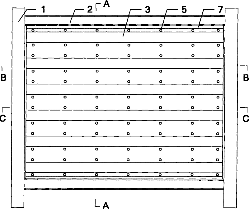
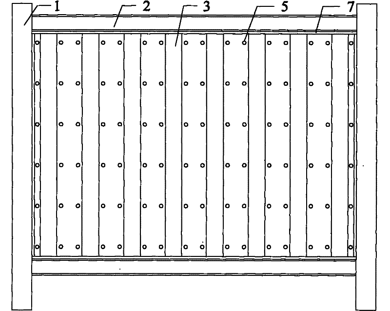
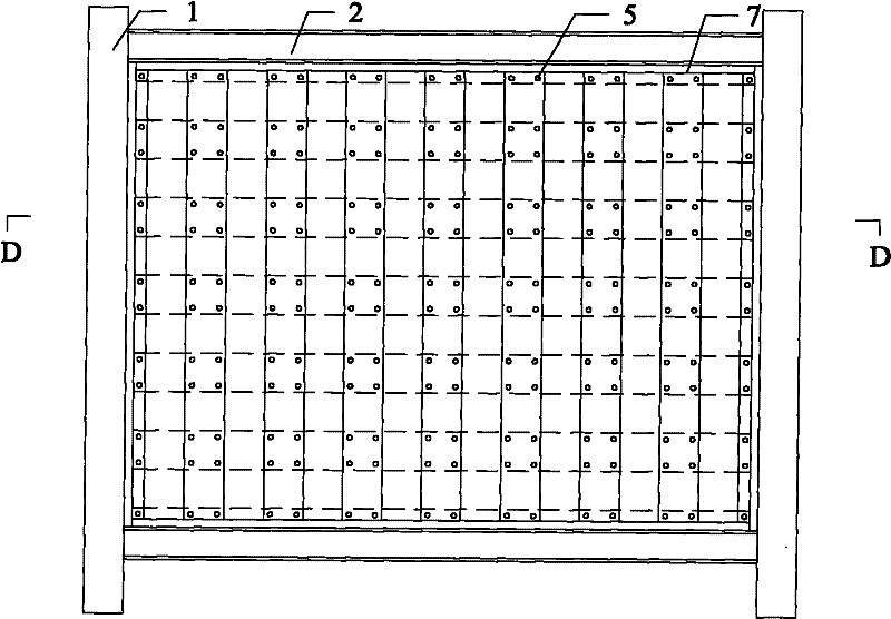
[0027] Attached below Figure 1-11 , Specifically explain this multi-layer steel plate composite shear wall.

[0028] A multi-layer steel plate composite shear wall, which is composed of flat steel plate, corrugated steel plate, C-shaped steel, high-strength bolts, thin-layer hard rubber backing plate and edge components, such as Figure 1-11 As shown, it contains the following components:

[0029] 1——Edge column;

[0030] 2——Edge beam;

[0031] 3——Corrugated steel plate;

[0032] 4-Flat steel plate;

[0033] 5——High-strength bolts;

[0034] 6——Thin hard rubber backing plate;

[0035] 7-C-shaped steel;

[0036] Among them, the edge column 1 and the edge beam 2 constitute the edge member; the corrugated steel plate 3 and the flat steel plate 4 are rolled by high ductility steel; Picture 11 As shown, the corrugated steel plate 3, the flat steel plate 4 and the edge members 1 and 2 are connected by C-shaped steel 7, the corrugated steel plate 3, the flat steel plate 4 and the C-shaped steel...


PUM


Abstract

The invention discloses a shear wall composed of multilayer steel plates, belonging to the technical field of structural engineering. The shear wall is characterized in that plain steel plates and the corrugated steel plates are combined in a laminating manner to form a shear wall combined of double-layer steel plates; or a plain steel plate is clamped between two corrugated steel plates to form a shear wall combined of three-layer steel plates; a thin-layer hard rubber pad is arranged between the plain steel plate and the corrugated steel plate; the plain steel plate, the corrugated steel plate and the thin-layer hard rubber pad are connected through a high-strength bolt; the pretightening force of the high-strength bolt enables the frictional force to be generated between the plain steel plate and the corrugated steel plate, thus the plain steel plate and the corrugated steel plate are commonly applied force under the action of the lateral force; under the action of strong earthquake, the relative slippage is generated because of larger displacement difference value inside the surfaces of the plain steel plate and the corrugated steel plate, and the plain steel plate and the corrugated steel plate are mutually restrained outside the surface all the time; and the plain steel plate and the corrugated steel plate are connected with the surrounding edge constructional members through C-shaped steel. The shear wall combined of multilayer steel plates can be used as a novel lateral force resistant constructional member in a high-rise building steel structure or other structures.

Description

Technical field [0001] The invention relates to a multi-layer steel plate combined shear wall, which belongs to the technical field of structural engineering. Background technique [0002] Steel plate shear wall is a new type of high-rise lateral force-resistant structural system. Compared with the traditional reinforced concrete shear wall, because the steel plate shear wall has the advantages of matching the rigidity and ductility of the steel frame and the effective exertion of the strength after buckling, it is established as the main lateral force unit in the design of steel frame Application status, while the ductility of reinforced concrete shear walls basically disappears after the concrete cracks, which is not conducive to the application of buildings in areas with high seismic intensity. Especially under the action of moderate or large earthquakes, the high ductility exhibited by the steel plate shear wall can greatly reduce the seismic action and effect, and it is a k...

Claims


Application Information

Patent Timeline
Patent Type & Authority Patents(China)
IPC IPC(8): E04B1/98E04B2/56
Inventor 郭彦林张博浩王小安
Owner WUXI RES INST OF APPLIED TECH TSINGHUA UNIV
Why Eureka
Try Eureka