Vehicle steering telescopic shaft

a telescopic shaft and steering shaft technology, applied in mechanical devices, couplings, transportation and packaging, etc., can solve the problems of nylon film abraded with a lapse of time of use, sharp increase in manufacturing costs, and more backlash, and achieve stable sliding load and high rigidity

Inactive Publication Date: 2005-11-24
NSK LTD
View PDF7 Cites 43 Cited by
  • Summary
  • Abstract
  • Description
  • Claims
  • Application Information

AI Technical Summary

Benefits of technology

[0008] The present invention has been contrived taking the circumstance as described above into consideration, and an object thereof is to provide a telescopic shaft for veh...

Problems solved by technology

However, in the former case, it is required to also suppress backlash to the minimum while suppressing the sliding load of the telescopic shaft to the minimum, so that it is unavoidable to select dies having slightly different over-pin sizes each by several microns to meet the size of the female shaft in the final cutting work for the processing, which results in sharp increase in the manufacturing cost.
In addition, the nylon film is abraded with a lapse of time of use to create more backlash in the direction or rotation.
Under the condition of a high temperature inside the engine room, the nylon film is changed in volume and the sliding resistance is conspicuously increased or the abrasion thereof is rapi...

Method used


Image

  • Vehicle steering telescopic shaft
  • Vehicle steering telescopic shaft
  • Vehicle steering telescopic shaft

Examples


first embodiment

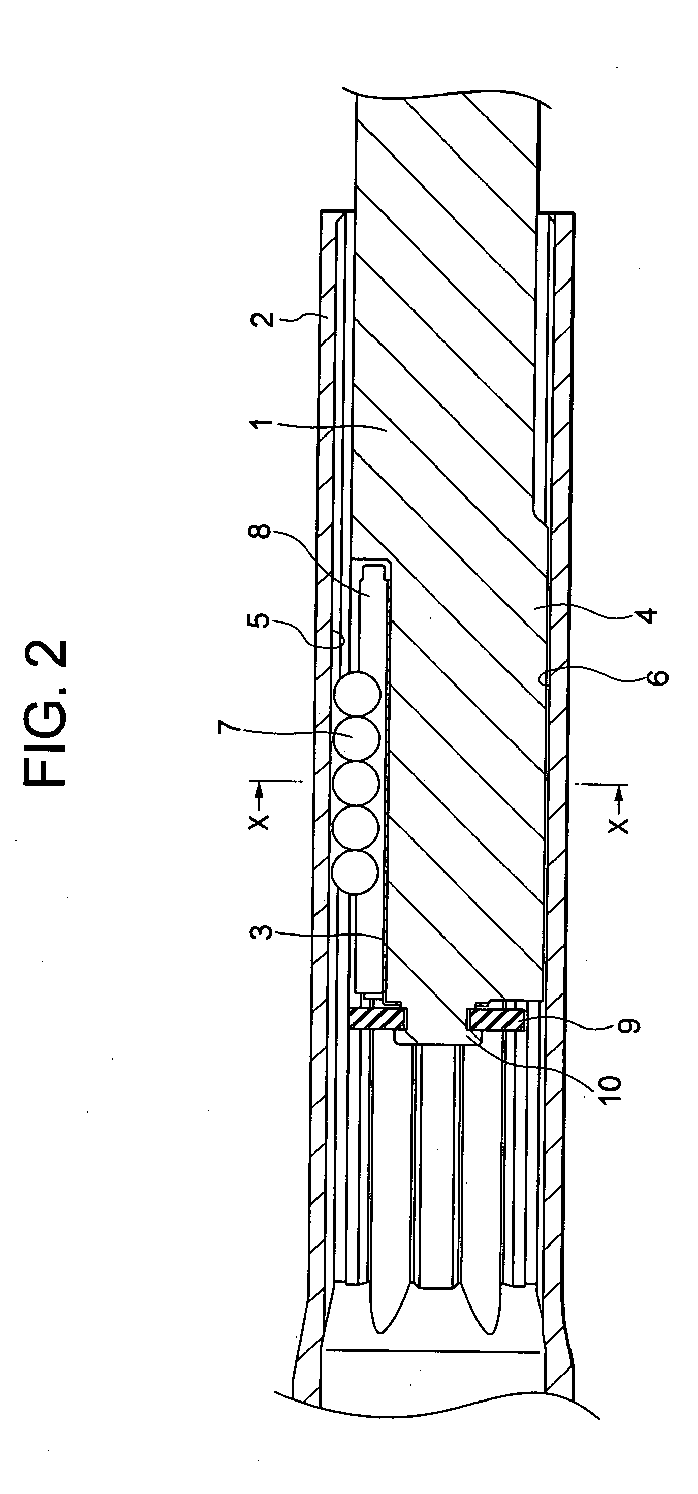
[0042]FIG. 2 is a cross-sectional view of a telescopic shaft for vehicle steering according to a first embodiment of the present invention, taken along the center line in the axial direction thereof, FIG. 3 is a cross-sectional view taken along the line X-X in FIG. 2, and FIG. 4 is a graph for showing a relationship between a stroke and a sliding load of the telescopic shaft for vehicle steering according to the first embodiment.

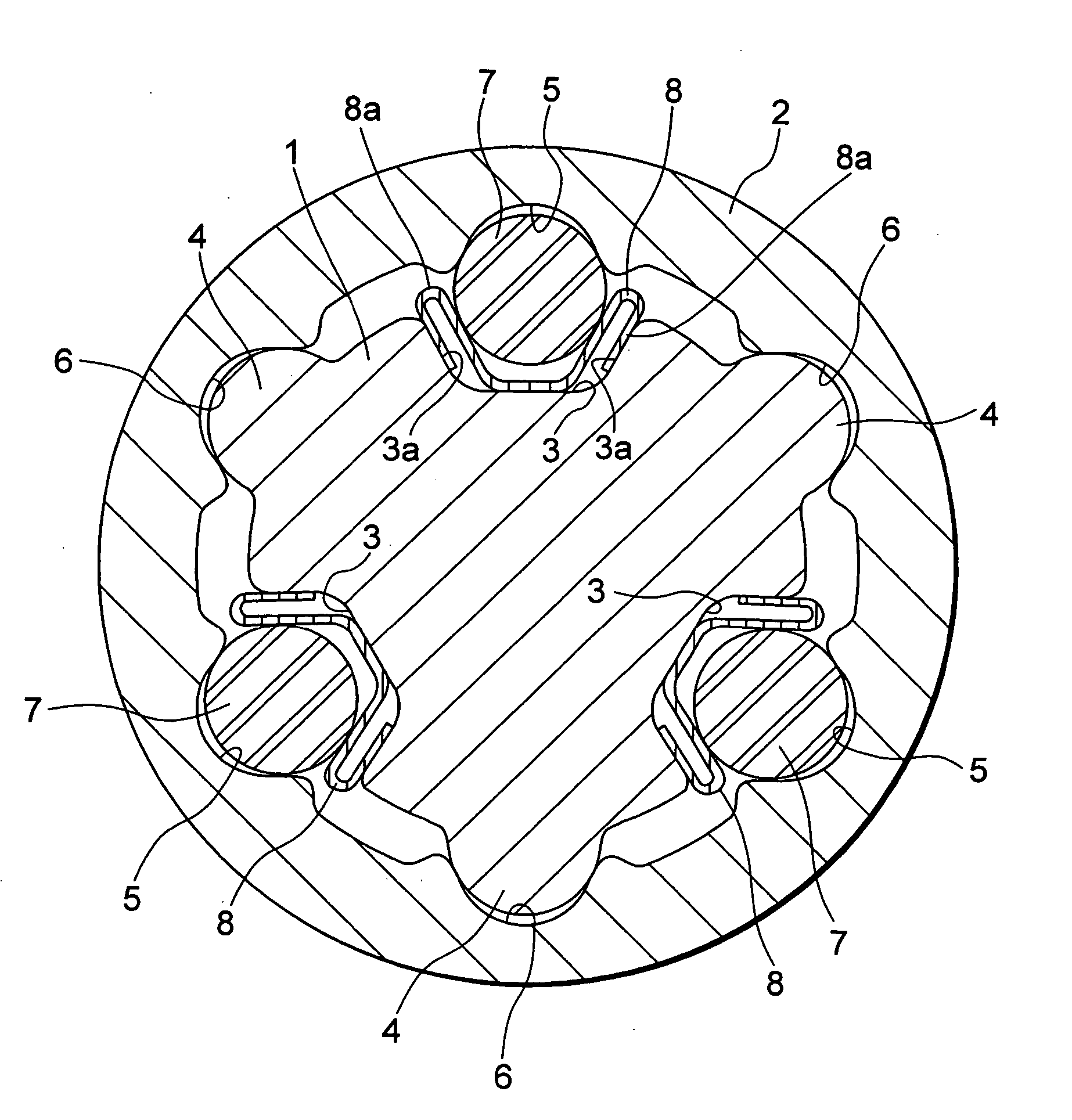
[0043] As shown in FIGS. 2 and 3, the telescopic shaft for vehicle steering (hereinafter called the telescopic shaft) is comprised of a male shaft 1 and a female shaft 2 which are mutually fitted to be unrotatable and slidable.

[0044] In the first embodiment, on the outer peripheral surface of the male shaft 1, there are formed three protrusions 4 extended in the axial direction at intervals of 120° in the circumferential direction, each having a substantially arcuate cross section. To be corresponding thereto, three grooves 6 extended in the axial directio...

second embodiment

[0068]FIG. 5 is a cross-sectional view of the telescopic shaft for vehicle steering according to a second embodiment of the present invention, taken along the center line in the axial direction thereof, and FIG. 6 is a cross-sectional view taken along the line X-X in FIG. 5. The same arrangements as those in the first embodiment are given the same referential numbers and symbols and the description thereof will be omitted.

[0069] The second embodiment of the present invention is different from the first embodiment in that a solid lubricant film 11 is formed on the outer peripheral surface of the male shaft 1. Since a contact resistance between the axial protrusion 4 and the axial groove 6 of the torque transmitting portion can be lowered by thus forming the solid lubricant film 11 on the outer peripheral surface of the male shaft 1, the total sliding load (which is a sliding load generated in a normal use in the structure of the present invention in which both rolling and sliding ar...

third embodiment

[0074]FIG. 7 is a cross-sectional view of the telescopic shaft for vehicle steering according to a third embodiment of the present invention, taken along the center line in the axial direction thereof, and FIG. 8 is a cross-sectional view taken along the line X-X in FIG. 7. The same arrangements as those in the second embodiment are given the same referential numbers and symbols and the description thereof will be omitted.

[0075] The third embodiment is different from the second embodiment in that the male shaft 1 is formed to have a hollow structure (a hollow portion 13) in order to reduce the weight of the entire telescopic shaft for vehicle steering and that, with this hollow structure of the male shaft 1, the stopper plate 12 is inserted in the hollow portion 13 of the male shaft 1 and then caulked. Other arrangements, functions and effects are the same as those in the second embodiment, and the description thereof will be omitted.

[0076] Note that in the third embodiment, the s...


PUM


Abstract

A telescopic shaft for vehicle steering which is assembled in a steering shaft of a vehicle and in which a male shaft 1 and a female shat 2 are fitted to each other to be unrotatable and slidable, comprises torque transmitting portions respectively provided in an outer peripheral portion of the male shaft 1 and in an inner peripheral portion of the female shaft 2 for transmitting torque when they are mutually in contact to rotate; and preloading portions each consisting of a rolling member 7 provided between the outer peripheral portion of the male shaft 1 and the inner peripheral portion of the female shaft 2 at a position different from that of the torque transmitting portion for rotating when the male shaft and the female shaft are relatively moved in the axial direction and an elastic member 8 provided adjacently to the rolling member 7 in the radial direction for applying preload on the male shaft 1 and the female shaft 2 through the rolling member 7.

Description

TECHNICAL FIELD [0001] The present invention relates to a telescopic shaft for vehicle steering. BACKGROUND ART [0002] Conventionally, a steering mechanism of a vehicle employs as its part a telescopic shaft which is constituted by a male shaft and a female shaft brought into spline fitting in order to absorb a displacement in the axial direction created upon running of the vehicle so as not to transmit the displacement or a vibration to a steering wheel. The telescopic shaft is required to reduce a backlash noise in a spline portion, to decrease backlash on the steering wheel, and to reduce a sliding resistance in a sliding movement in the axial direction. [0003] For these reasons, a nylon film is coated on the spline portion of the male shaft of the telescopic shaft and, furthermore, grease is applied on the slide portion, thereby absorbing or mitigating metallic noise, metallic drumming sound, or the like, and at the same time, reducing the sliding resistance and backlash in the ...

Claims


Application Information

Patent Timeline
IPC IPC(8): B62D1/185B62D1/16F16C3/035F16C13/00F16C19/26F16C25/08F16C29/04F16C29/12F16C33/30F16C33/32F16C33/62F16C33/64F16D3/06
CPCB62D1/185F16C3/035F16C29/04F16C29/12F16D3/065F16C33/32F16C33/62F16C33/64F16C33/30F16C29/123F16C29/007F16C2326/24
Inventor YAMADA, YASUHISA
Owner NSK LTD
Why Eureka
Try Eureka