
Furnace device for eliminating volatile organic compounds (VOCs)

a technology of volatile organic compounds and furnaces, which is applied in the direction of solid fuel combustion, lighting and heating apparatuses, and combustion types, etc., can solve the problems of volatile organic compounds, wasting space, and polluting the environment, and achieves the effect of small size and low cos

Inactive Publication Date: 2005-11-24
CHU MIN YI +1
View PDF4 Cites 3 Cited by
  • Summary
  • Abstract
  • Description
  • Claims
  • Application Information

AI Technical Summary

Benefits of technology

[0010] The main objective of the prevent invention is to provide a furnace device to eliminate volatile organic compounds, which has low cost and small size, and is suitable for exhaust gases with low-concentrations of volatile organic compounds.

Problems solved by technology

These volatile organic compounds are hazardous to the human body and pollute our environment.
When the quantity of volatile organic compounds is low or the compounds are worthless, other methods destroy the volatile organic compounds.
Besides wasting space and being expensive, the absorbing device is a low capacity device and cannot be used in every factory.
Additionally, regenerating the active carbon filtering sheets is also expensive, and the active carbon filtering sheets need to be replaced with new ones often because regenerating the active carbon filtering sheets quickly becomes ineffective.
Therefore, electric consumption of the air-extracting system is inevitably high and the volatile organic compounds attached to the filtering sheets may cause secondary pollution if the volatile organic compounds are not properly treated.
However, the cost to operate the catalytic burning device is high, and the holes are easily clogged with ash after burning, which causes the device to malfunction.
The methods and devices to remove volatile organic compounds from exhaust gas still have some problems.

Method used


Image

  • Furnace device for eliminating volatile organic compounds (VOCs)
  • Furnace device for eliminating volatile organic compounds (VOCs)
  • Furnace device for eliminating volatile organic compounds (VOCs)

Examples


Embodiment Construction

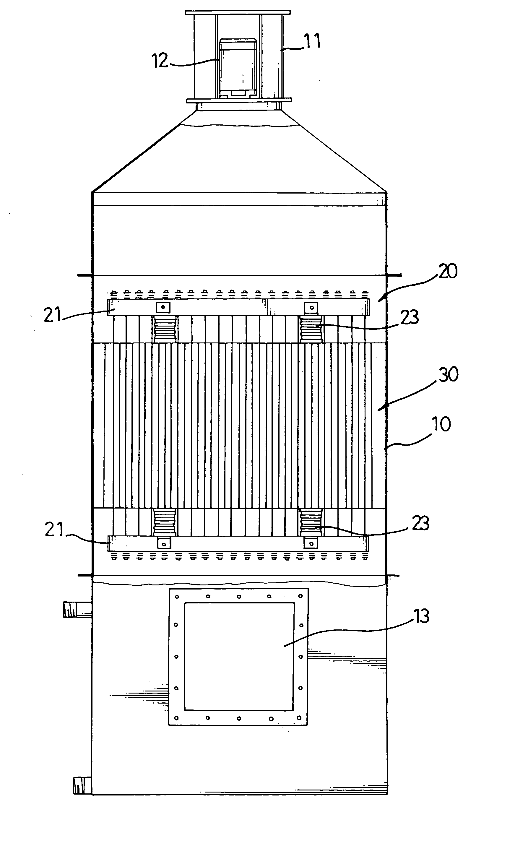
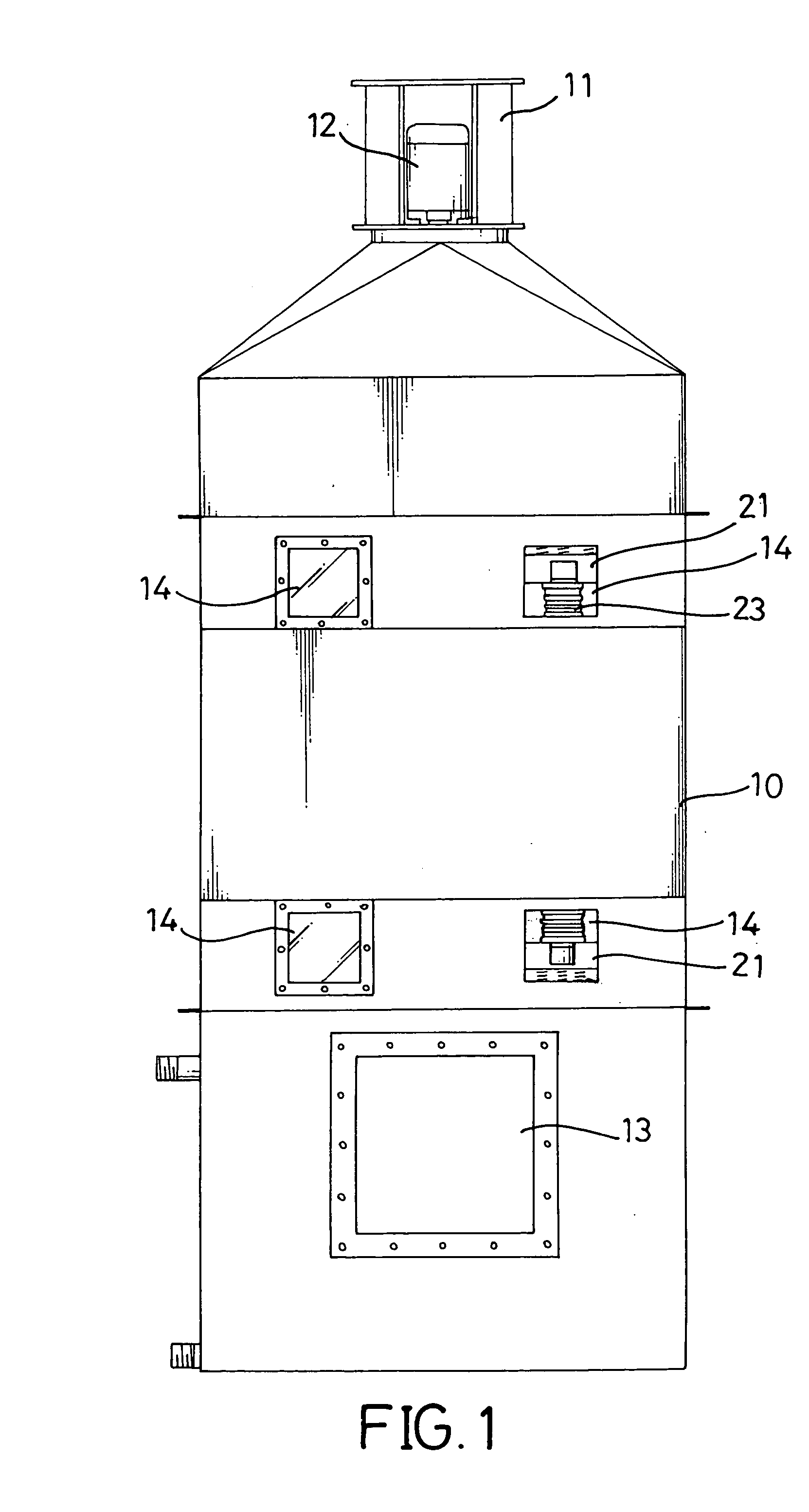
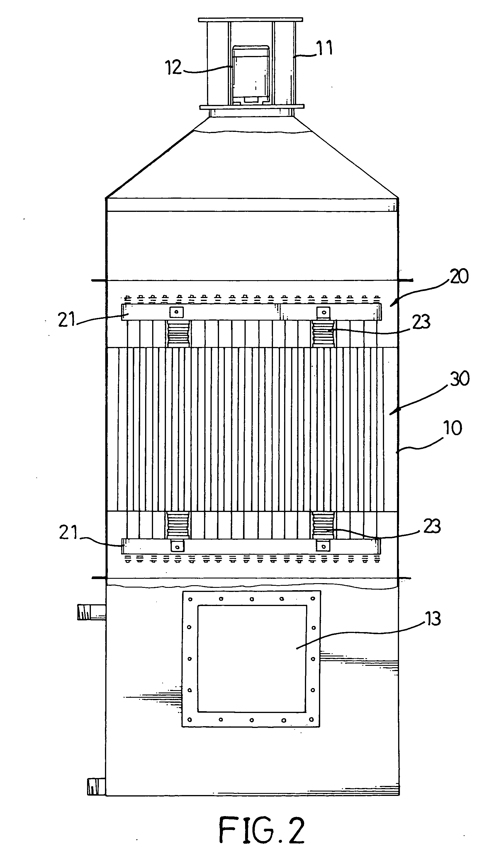
[0017] A furnace device for eliminating volatile organic compounds in exhaust gas comprises a hollow body, a gas inlet, a gas outlet, an arc generator, two positioning plates and multiple optional damping devices. The hollow body has a top and a bottom. The gas inlet is defined near the bottom of the hollow body, and the gas outlet is defined at the top of the hollow body. The arc generator is mounted between the gas inlet and gas outlet and generates arcs to burn the volatile organic compounds when the exhaust gas enters the furnace device. The two positioning plates clamp and hold the arc generators in place. The multiple optional damping devices are mounted between the arc generator and the two positioning plates.

[0018] With reference to FIGS. 1 to 3, a preferred embodiment of the furnace device in accordance with the present invention comprises a body (10), a positioning device (20), and an arc generator (30).

[0019] The body (10) is a hollow cylinder with a flat bottom (not nu...


PUM


Abstract

This invention relates to a furnace device for eliminating volatile organic compounds in exhaust gas. The furnace device has a hollow body (10) with a gas inlet (13) and a gas outlet (11), a positioning device (20) mounted inside the body (10) and an arc generator (30) attached to the positioning device (20). The arc generator (30) has multiple cylindrical chambers (31) for accommodating the exhaust gas and multiple central rods (32) respectively penetrating through the multiple cylindrical chambers (31). In each chamber (31), an inner periphery of the chamber (31) serves as an electrode, and the central rod (32) serves as another electrode. When an effective potential difference is applied to the electrodes, arcs are generated between the inner periphery of the chamber (31) and the central rod (32) inside the chamber (31). Thereby, volatile organic compounds in the exhaust gas are burned and decomposed effectively and completely by the generated arcs.

Description

BACKGROUND OF THE INVENTION [0001] 1. Field of the Invention [0002] The present invention relates to a furnace device for eliminating volatile organic compounds (VOCs), and more particular a furnace device that uses arcs to burn the volatile organic compounds in an exhaust air. [0003] 2. Description of Related Art [0004] Exhaust gases from most factories contain volatile organic compounds such as hydrocarbon compounds having oxygen, nitrogen, sulfur or halogen. These volatile organic compounds are hazardous to the human body and pollute our environment. Conventional methods for eliminating the volatile organic compounds from the exhaust gases are absorbing, chemical oxidation, burning, bio-oxidation and condensing methods. If quantity of volatile organic compounds in the exhaust gas is large, absorbing and condensing methods are carried out to recycle the volatile organic compounds. When the quantity of volatile organic compounds is low or the compounds are worthless, other methods ...

Claims


Application Information

Patent Timeline
IPC IPC(8): F23G5/00F23G7/06
CPCF23G2204/201F23G7/063
Inventor CHU, MIN-YITING, CHIEN-BANG
Owner CHU MIN YI
Learn More