
High aspect ratio, high mass resolution analyzer magnet and system for ribbon ion beams

Active Publication Date: 2005-11-24
WHITE NICHOLAS R +1
View PDF1 Cites 64 Cited by
  • Summary
  • Abstract
  • Description
  • Claims
  • Application Information

AI Technical Summary

Benefits of technology

[0063] An additional aspect of the invention provides for curving the profile of the bounding steel surfaces, and curving the entrance and exit edges of the steel yoke, so as to minimize distortions and aberrations in the shape of the ion beam.

Problems solved by technology

However, for large ribbon-shaped beams generally and particularly for those beams of high Perveance, this type of magnetic mass analysis and ion beam purification has become ever-more difficult and costly.
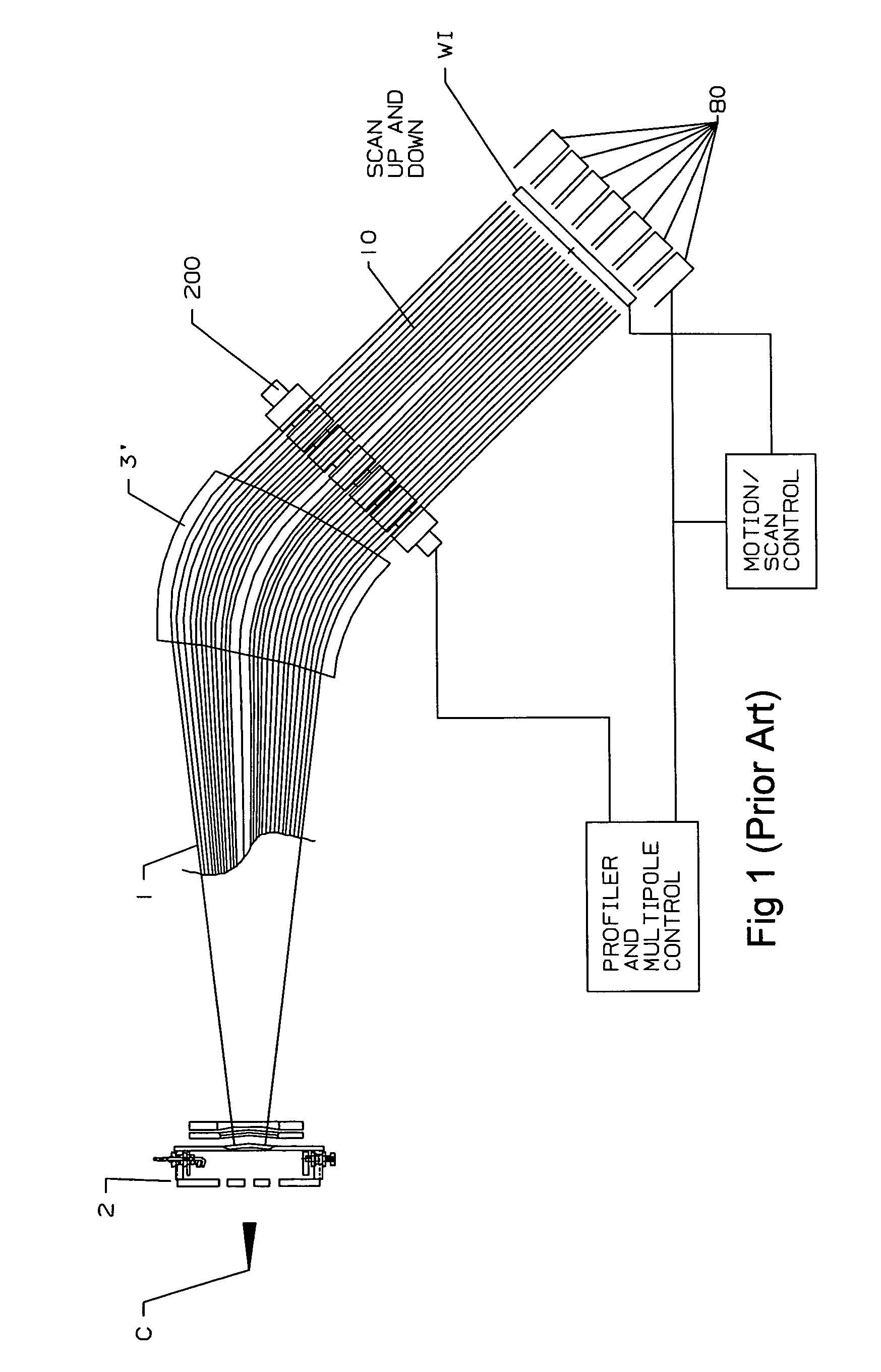
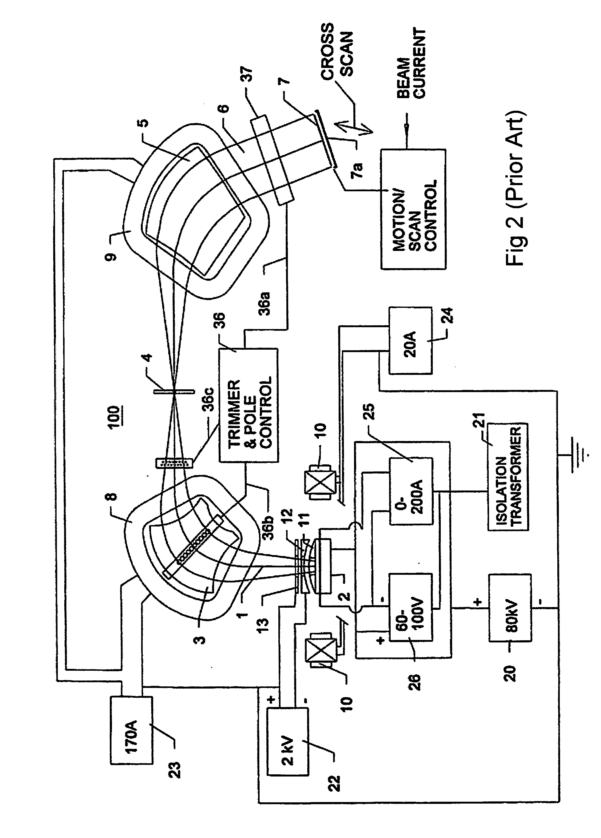
Unfortunately however, this two-magnet system has severe drawbacks: it is complex and expensive; and is only manufactured to produce ribbon ion beams up to 300 mm in size (See Prior Art FIG. 2, reproduced from U.S. Pat. No. 5,350,926).
However, it is noted that analyzer magnets having a resolving power greater than about 30 have only recently and imperfectly been introduced and utilized in such systems.
Of these, only one commercially sold ion implanter apparatus for flat panel displays has a resolving power of more than 30; and it suffers from major drawbacks including a high power consumption, extreme weight, and stray magnetic fields, as described herein.
One of the major difficulties of achieving high resolving power in a single magnet bending a ribbon beam is the very likely possibility of creating a serious second-order aberration, which will cause a distortion of the shape of the ion beam [see for example, the discussion of this problem in the White et al., AIP publication cited above].
The other result is to compromise the effective aspect ratio of the beam through which the flat glass panel (or other workpiece) is scanned, thereby requiring a longer scan distance and reducing the implantation efficiency of the scan.
However, while a ‘window-frame’ magnet can generate the required magnetic field internally within the yoke, it also concomitantly creates on the outside of the yoke structure a ‘naked’ dipole magnet, which produces a very strong fringing field capable of extending great distances from the magnet.
The problems Associated with Concomitantly Generating a ‘Fringe Field’
Among the known drawbacks of concomitantly generating a strong ‘fringe field’ are: (i) safety and regulatory problems associated with the exposure of personnel to high magnetic fields, particularly for persons wearing pacemakers; (ii) the effects of the stray magnetic field on the performance of the ion source in the apparatus; (iii) the effects of the stray magnetic fields upon cathode ray tubes (which can be avoided by the use of flat-panel displays); and (iv) the effects upon system adjustments performed during the operation of sensitive electronics.
In addition, the stored energy and the power consumption of a window-frame magnet (generating a fringe field) can be very great; and, in combination with the magnetic shielding required to abate these problems, the weight of the entire apparatus and system can become very great.
Moreover, the fringe field is many more times more powerful and extensive in window-frame magnets of the type disclosed by Nissin and by Benveniste, because current carrying coils surround almost the entire magnet structure; the field clamp approach is therefore both more needed and more difficult to deploy effectively.

Method used


Image

  • High aspect ratio, high mass resolution analyzer magnet and system for ribbon ion beams
  • High aspect ratio, high mass resolution analyzer magnet and system for ribbon ion beams
  • High aspect ratio, high mass resolution analyzer magnet and system for ribbon ion beams

Examples


first preferred embodiment

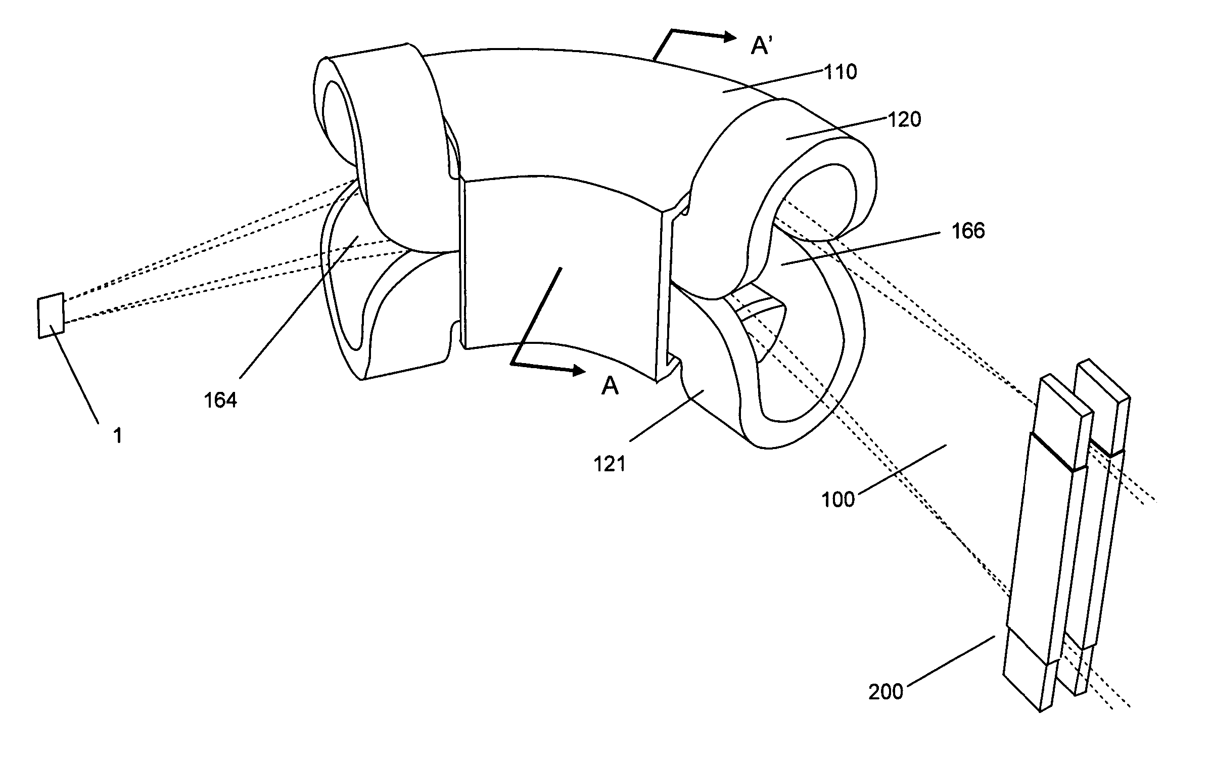
[0106] A first preferred format for the present invention is illustrated by FIGS. 4, 5 and 6. As seen therein, a single deflection magnet bends the ribbon-shaped ion beam through an angle of at least 45 and preferably less than 110 degrees. The ferromagnetic yoke of the dipole magnet is essentially rectangular in overall cross-sectional appearance; although the true shape of the yoke may be slightly modified to enhance the ion optics, as will be described later herein.

A. The Axis and Intended Pathway for the Traveling Ribbon Ion Beam

[0107] For descriptive purposes, it is presumed that the major beam axis is vertical, and that the beam is traveling horizontally. The intended pathway of the center of the beam is referred to as the desired “beam axis”; and the “beam axis” comprises a first straight section, a curved section and a second straight section. This curvilinear beam axis lies in a plane, the midplane of the intended pathway.

[0108] Clearly, the beam axis provides the intend...


PUM


Abstract

The present invention provides a windowframe magnet having an aligned array of paired bedstead coils in mirror symmetry can bend a high aspect ratio ribbon ion beam through angle of not less than about 45 degrees and not more than about 110 degrees, and can focus it through a resolving slot for mass analysis. The long transverse axis of the beam, which can exceed 50% of the bend radius, is aligned with the generated magnetic field. The array of paired bedstead coils provide tight control of the fringing fields, present intrinsically good field uniformity, and enable a manufacture of much lighter construction than other magnet styles conventionally in use in the ion implantation industry. Within the system of the present invention, the ribbon beam is refocused with low aberration to achieve high resolving power, which is of significant value in the ion implantation industry. System size is further reduced by using a small ion source and a quadrupole lens to collimate the beam after expansion and analysis. There is no fundamental limit to the aspect ratio of the beam that can be analyzed.

Description

PRIORITY CLAIM [0001] The present invention was first filed on May 18, 2004 as U.S. Provisional Patent Application Ser. No. 60 / 571,965 entitled “High Aspect Ratio, High Mass Resolution Magnet For Ribbon Beams”. The priority of this first filing is expressly claimed pursuant to 35 U.S.C. 119(e).FIELD OF THE INVENTION [0002] The present invention is concerned generally with mass-analyzing ribbon shaped ion beams; and is directed specifically to novel high resolution magnets able to bend a high aspect ratio ribbon ion beam at a pre-chosen angle and focus the ion beam for mass analysis with high resolving power and high acceptance. BACKGROUND OF THE INVENTION [0003] In the field of ion beam systems, it is sometimes desired to generate purified ion beams in the form of ribbon-shaped beams. These ribbon beams are commonly used in ion implanter apparatus and implantation systems where a workpiece (such as a silicon wafer or flat panel display) is moved through the ion beam. In these instan...

Claims


Application Information

Patent Timeline
IPC IPC(8): H01J37/05H01J37/317H01J49/20
CPCH01J37/05H01J49/30H01J37/3171
Inventor WHITE, NICHOLAS R.CHEN, JIONG
Owner WHITE NICHOLAS R
Learn More