Linear suspension spring

Inactive Publication Date: 2005-11-24
DOVE JASON L
View PDF18 Cites 19 Cited by
  • Summary
  • Abstract
  • Description
  • Claims
  • Application Information

AI Technical Summary

Benefits of technology

[0010] An advantage of the disclosed invention is that, unlike suspension spring apparatus in the past that produce a bending moment that is a function of the degree of deflection through which the wheel has moved, the springs centerline adjusts so as to be directed toward the point of stress force produced by the wheel motion. There is no need for a complex curved and/or compound spring, and the suspension can be engineered so as to have optimum dampening by the shock absorber throughout the motion of the wheel. Another advantage is that the spring is substantially free of transverse deformation, which shortens the life of the spring and creates vibrations that are ineffectively dam

Problems solved by technology

In the static loaded state, the piston rod of the shock absorber is reported to be largely free of shear forces, however, the configuration does not ameliorate the problem during the non-static state.
When the wheel moves either upward or downward, the spring alignment is lost because the alignment of the resistance point does not adjust for the position change of the wheel.
Angling the spring possibly helps under static conditions, but because the stress point changes as the control arm pivots, the spring is often out of alignment to produce the most effective resistance, and the level of performance is not as good as it would be if the spring were properly aligned.
While the coil-over strut has the apparent advantage that the spring is substantially coaxial with the helical compression spring, it is limited in that the shock absorber must be sufficiently robust to serve as both a pneumatic cylinder dampener and as the

Method used


Image

  • Linear suspension spring
  • Linear suspension spring
  • Linear suspension spring

Examples


Embodiment Construction

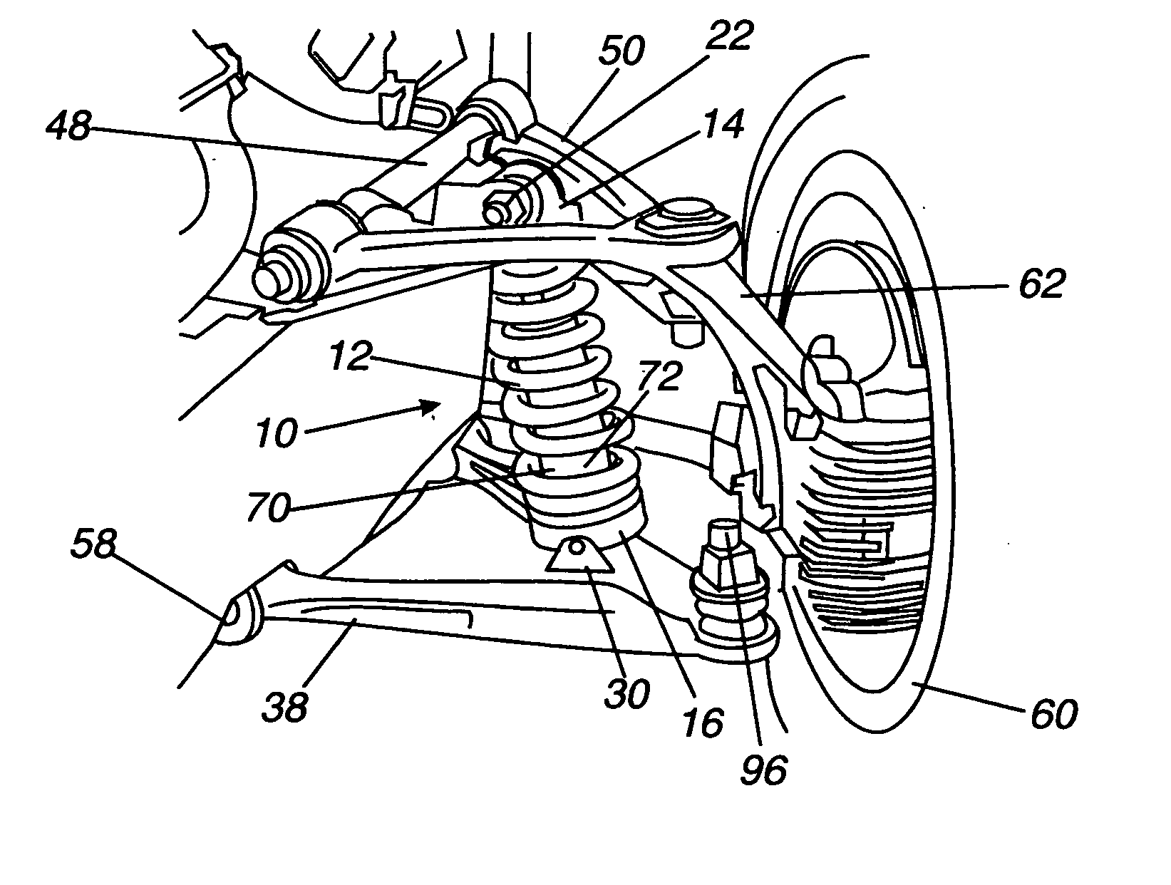
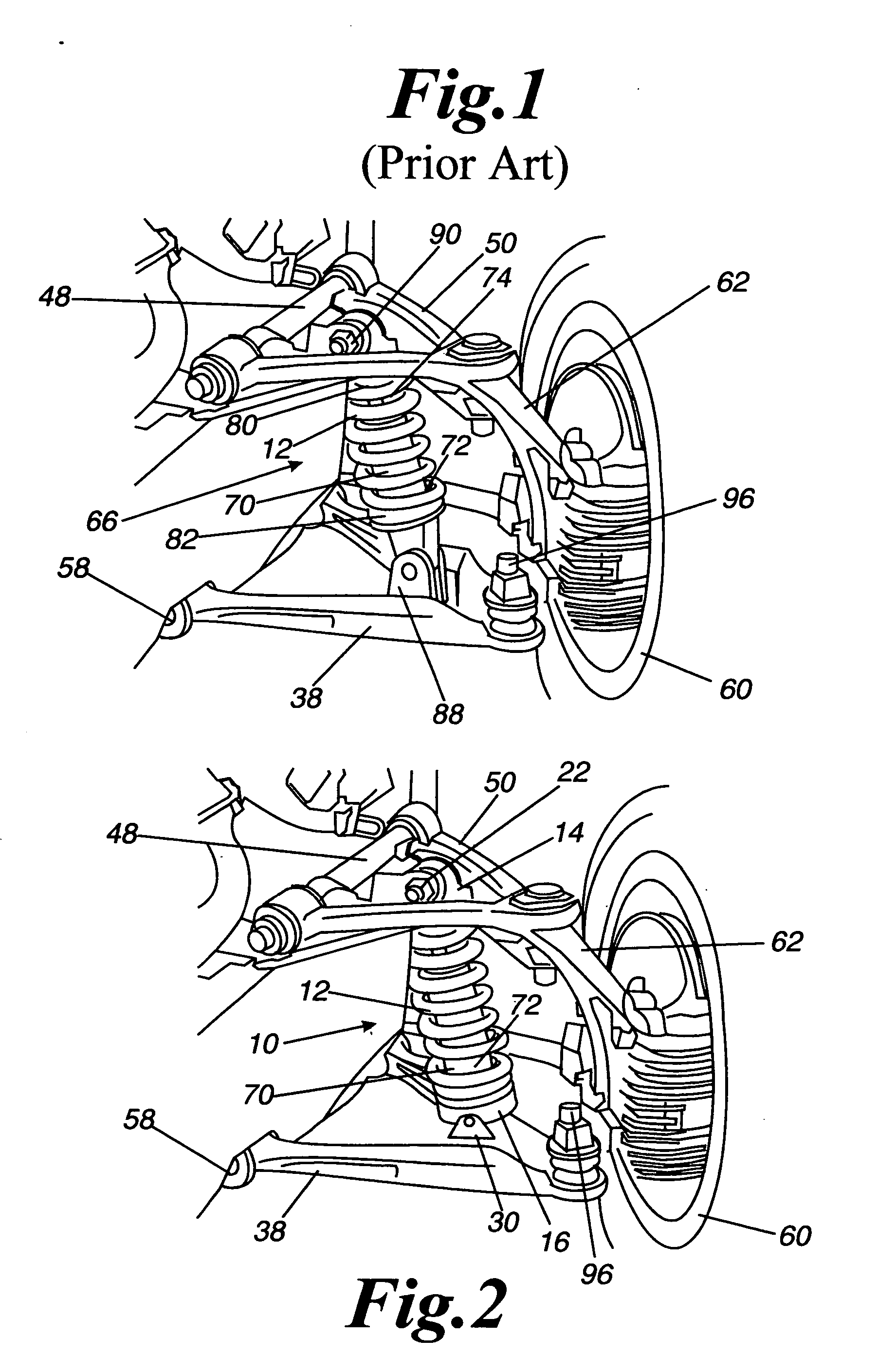
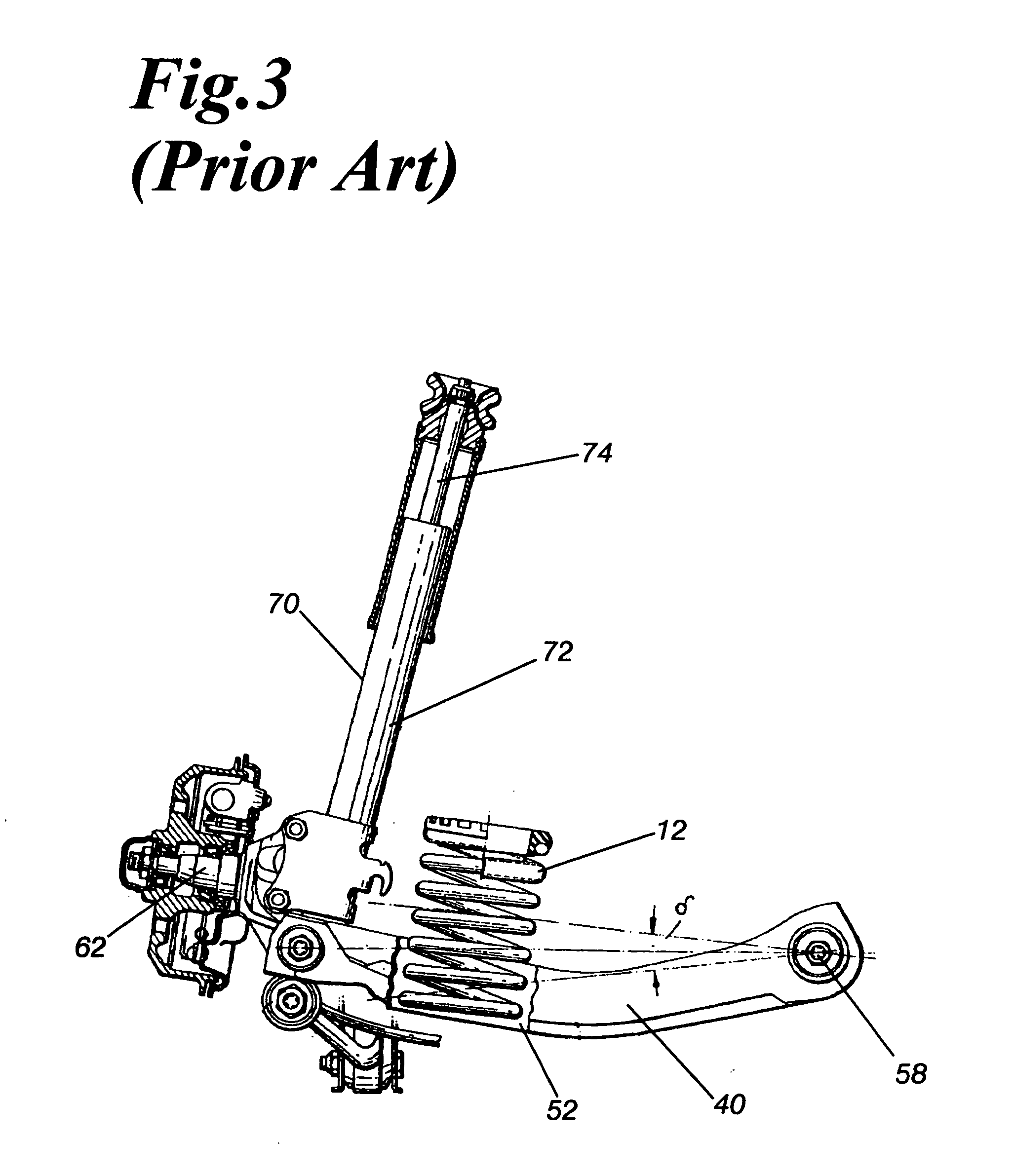
[0032] The invention is a linear suspension spring apparatus for a vehicle, wherein the suspension spring is mounted between a pivoting lower seat and a pivoting upper seat. The suspension spring is a helical compression spring, and characteristically of helical compression springs, the spring resists deformation from the centerline, as well as from compression. Deformation away from the centerline produces curvature of the spring, so that the coils on one side of the spring will be more compressed and the coils on the other side are more expanded. The greater the compression, the greater the force the spring exerts. Therefore, when the spring is mounted between two seats having substantially planar bases, a compression spring exerts equalizing forces on the opposing seats to minimize the compression forces, and this minimum is attained when the opposing seats are substantially parallel to each other. In the suspension apparatus, one of the pivoting seats is mounted to an articulati...


PUM


Abstract

The invention is a suspension spring apparatus for a vehicle wherein the suspension spring maintains a linear alignment irrespective of the position of the articulating strut, where the articulating strut is selected from the group consisting of: control arms, axle arms, solid axles, adjustable spring tensioning devices, and longitudinal struts. The apparatus is comprised of a compression spring mounted between a pivoting lower seat and a pivoting upper seat, where the pivoting lower seat is coupled to the articulating strut and the pivoting upper seat is coupled to a support element. The support element is static, and serves to support the suspension system, and to distribute the forces generated by the suspension system. The pivoting lower seat and the pivoting upper seat can, in combination, pivot through substantially the same plane as the articulating strut, such that when there is a change in angle of the articulating strut with respect to the support element there is a commensurate change in the pivoting lower seat and the pivoting upper seat. The compensation maintains the compression spring aligned linearly between the pivoting lower seat and the pivoting upper seat. Compression and expansion occurs along the centerline of the spring, and there is no transverse curvature, or other deformation of the spring.

Description

BACKGROUND OF THE INVENTION [0001] 1. Field of the Invention [0002] The present invention relates to a helical compression spring for a vehicle suspension, and more particularly to a mounting system for the helical compression spring that maintains the spring in a linear orientation over the entire range of compression. [0003] 2. Description of the Related Arts [0004] In general, a vehicle suspension is provided with a substantially helical compression spring, where the compression spring works in concert with a shock absorber. The compression spring can be substantially coaxial to a telescoping strut, or a shock absorber that simultaneously serves as a telescoping strut. In the case where the compression spring is mounted having an annular shock absorber (i.e., a coil-over or MacPherson strut), the spring is typically held between a lower spring seat that is affixed to the piston, and an upper seat that is usually affixed to the frame. In this configuration, the shock absorber has ...

Claims


Application Information

Patent Timeline
IPC IPC(8): B60G3/18B60G3/20B60G11/15B60G11/16B60G15/00
CPCB60G3/20B60G11/15B60G2204/1244B60G2202/12B60G2204/124B60G11/16
Inventor DOVE, JASON L.
Owner DOVE JASON L
Why Eureka
Try Eureka