Generator-motor

Inactive Publication Date: 2005-11-24
TOYOTA JIDOSHA KK
View PDF14 Cites 26 Cited by
  • Summary
  • Abstract
  • Description
  • Claims
  • Application Information

AI Technical Summary

Benefits of technology

[0035] Therefore, according to the present invention,

Problems solved by technology

Accordingly, it is difficult to achieve smaller size of the starter-generator.
In particular, when a control circuit to control a generator installed in an engine is incorporated in the generator, a similar problem tends to arise.
As Japanese Patent Laying-Open No. 2-266855 does not clearly disclose a position where an electrode included in the power module is arrang

Method used


Image

  • Generator-motor
  • Generator-motor
  • Generator-motor

Examples


Embodiment Construction

[0047] In the following, embodiments of the present invention will be described in detail with reference to the figures. It is noted that the same reference characters refer to the same or corresponding components in the figures.

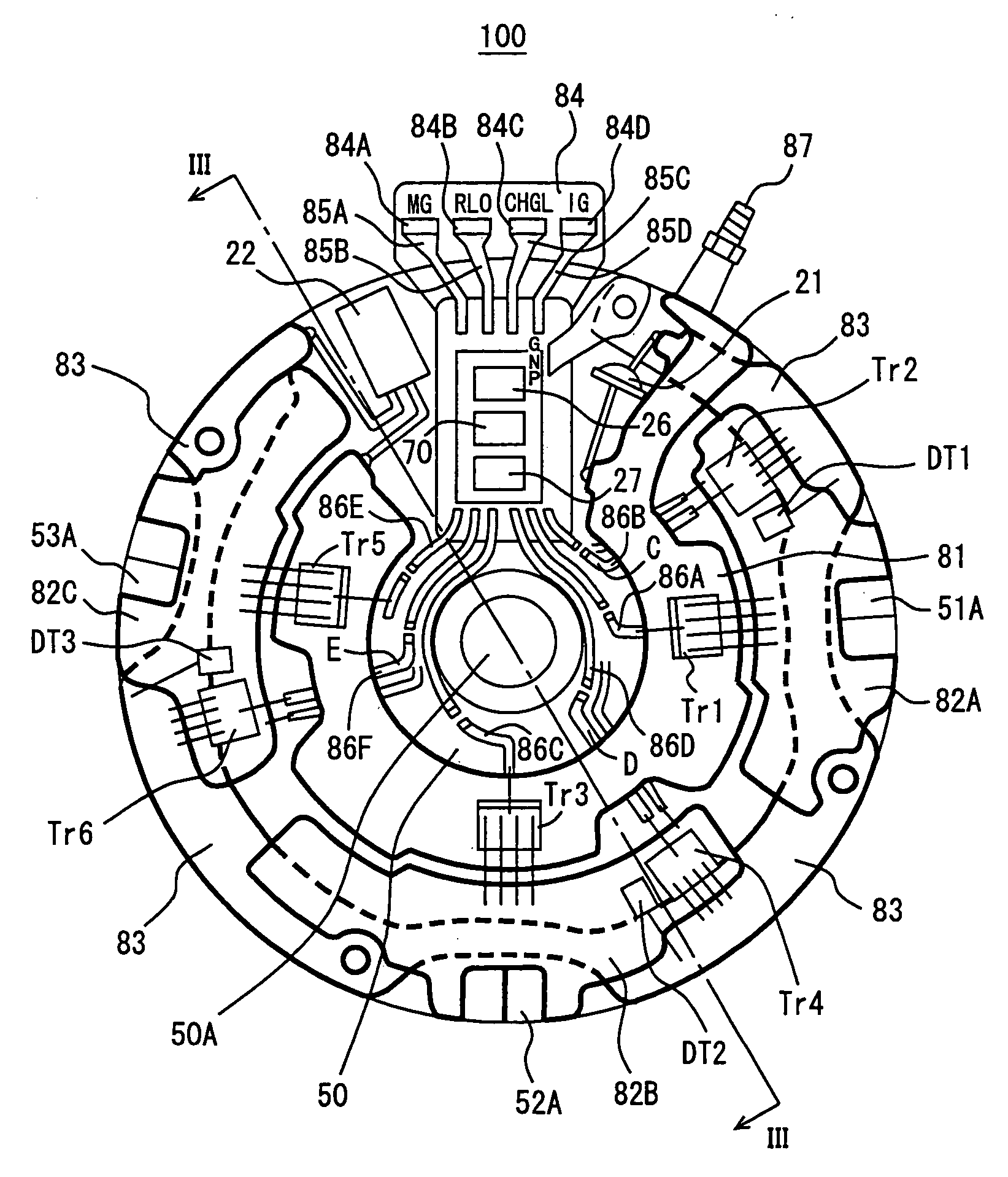
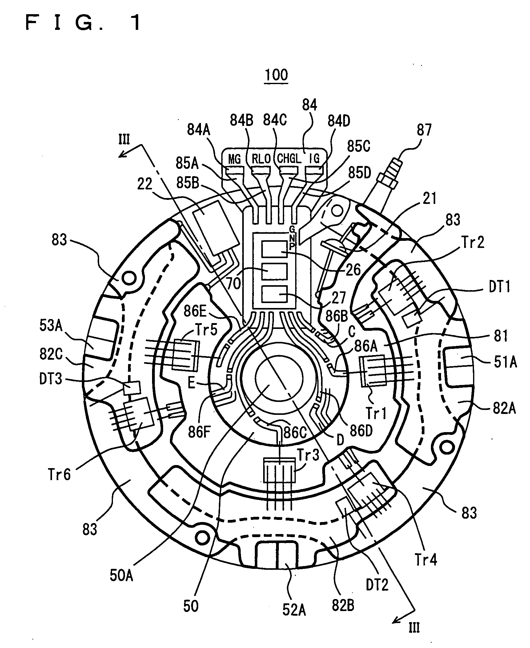
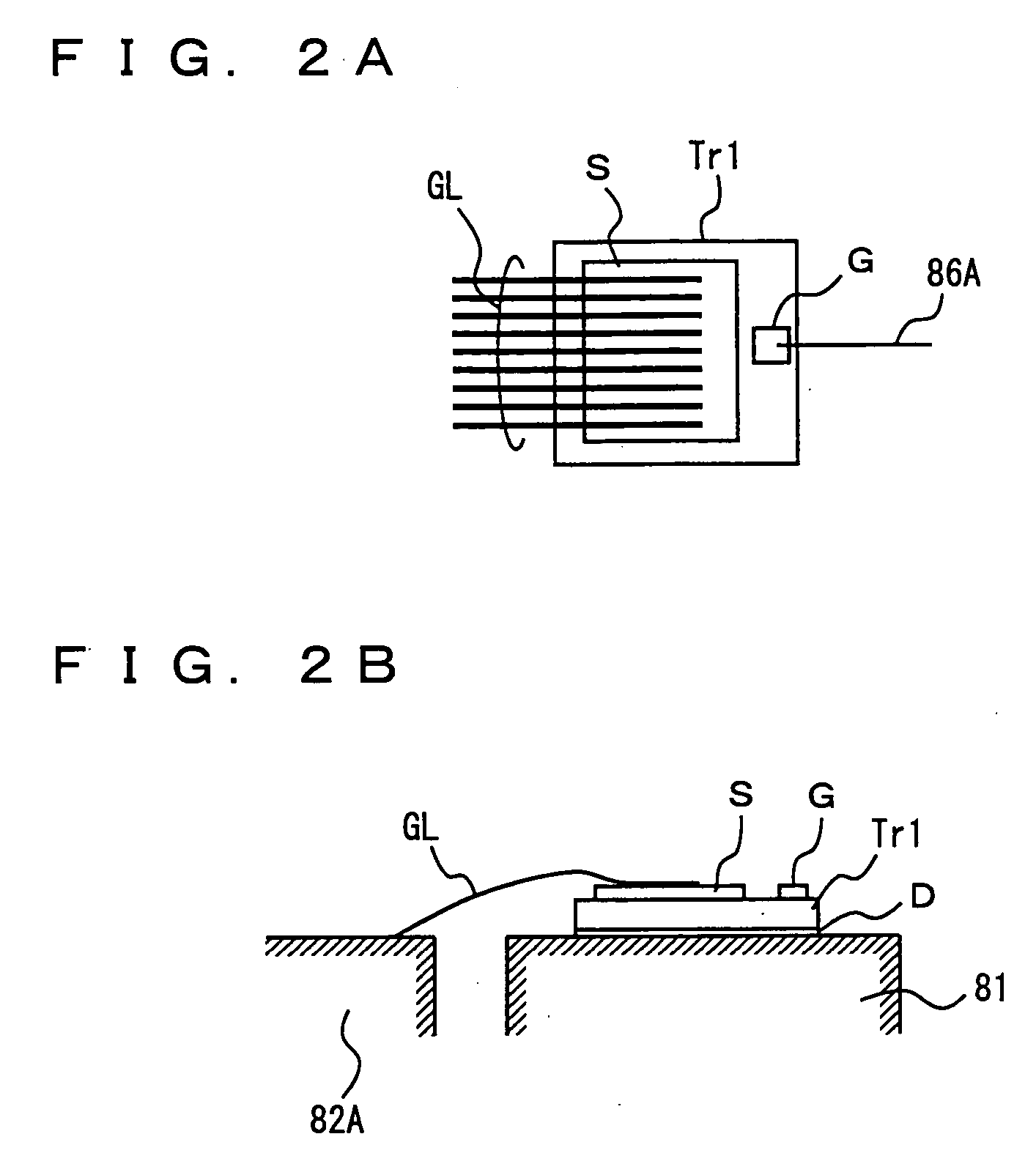
[0048] Referring to FIG. 1, a generator-motor 100 according to the present invention includes Zener diodes 21, DT1 to DT3, MOS transistors Tr1 to Tr6, a power source 26, an MOS driver 27, an alternator 50, a custom IC 70, electrode plates 81, 82A to 82C, 83, a substrate 84, terminals 84A to 84D, and wires 85A to 85D, 86A to 86D.

[0049] Electrode plates 81, 82A to 82C, 83 and substrate 84 are formed on an end surface of alternator 50. Electrode plate 81 has a substantial U-shape, and is provided around a rotation shaft 50A of alternator 50. Electrode plates 82A to 82C are provided so as to substantially form a U-shape outside electrode plate 81 to surround electrode plate 81. Electrode plates 82A to 82C are arranged at prescribed intervals from each other. E...


PUM


Abstract

A generator-motor includes an alternator, electrode plates, a substrate, MOS transistors, and an MOS driver. Electrode plates are arranged on an end surface of the alternator so as to substantially form a U-shape to surround a rotation shaft of the alternator. MOS transistors are arranged on the electrode plate, while MOS transistors are arranged on the electrode plates respectively. The MOS driver is provided on the substrate arranged in a substantially U-shaped notch, and controls turn-on/off of the MOS transistors.

Description

TECHNICAL FIELD [0001] The present invention relates to a generator-motor including a control device on an end surface, and more particularly to a compact generator-motor. BACKGROUND ART [0002] Japanese Patent Laying-Open No. 2-266855 discloses a starter-generator attaining a function as a three-phase motor starting an engine mounted on a vehicle and a function as a three-phase AC generator charging a battery. [0003] Referring to FIG. 9, a starter-generator 300 disclosed in Japanese Patent Laying-Open No. 2-266855 includes a motor unit 301 and a drive unit 302. Motor unit 301 includes a stator and a rotor. Drive unit 302 is provided on an end surface 301A of motor unit 301. Drive unit 302 includes a cylindrical member 302A and a power module 302B. Power module 302B is formed on a surface of cylindrical member 302A. That is, power module 302B is arranged in a direction perpendicular to a radial direction 303 of cylindrical member 302A and in a longitudinal direction 304 of a rotation...

Claims


Application Information

Patent Timeline
IPC IPC(8): H02K11/04
CPCH02K11/048H01L2224/40H01L2224/73265H01L2924/13055H02K11/05H01L2924/00
Inventor KUSUMI, HIDETOSHI
Owner TOYOTA JIDOSHA KK
Why Eureka
Try Eureka