Low power consumption permanent magnet biased internal rotor radial magnetic bearing

A permanent magnet bias, low power consumption technology, applied in bearings, shafts and bearings, mechanical equipment, etc., can solve the problems of weakening the suction force of permanent magnets on the rotor shaft, excessive loss of magnetomotive force, and large excitation current, etc., to achieve Save power consumption, ensure operation stability, and reduce power consumption

Inactive Publication Date: 2006-09-27
BEIHANG UNIV
View PDF0 Cites 1 Cited by
  • Summary
  • Abstract
  • Description
  • Claims
  • Application Information

AI Technical Summary

Problems solved by technology

However, some of the current permanent magnet bias inner rotor radial magnetic bearing structures are based on ordinary radial electromagnetic bearings, and permanent magnets are placed upward on the electromagnetic magnetic circuit, so that the magnetic flux generated by the control coil must pass through the permanent magnets. Due to the large reluctance of the permanent magnet, the control coil needs a large excitation current to generate a certain electromagnetic flux. In addition, some structures directly connect the permanent magnet to the stator laminated core, so that the permanent magnet magnetic circuit passes through the stator core. Excessive magnetomotive force will be lost, thus greatly weakening the attraction of the permanent magnet to the rotor shaft; due to the above defects, the existing permanent magnet bias magnetic bearings have the disadvantages of large power consumption, large volume and heavy weight

Method used


Image

  • Low power consumption permanent magnet biased internal rotor radial magnetic bearing
  • Low power consumption permanent magnet biased internal rotor radial magnetic bearing
  • Low power consumption permanent magnet biased internal rotor radial magnetic bearing

Examples


Embodiment Construction

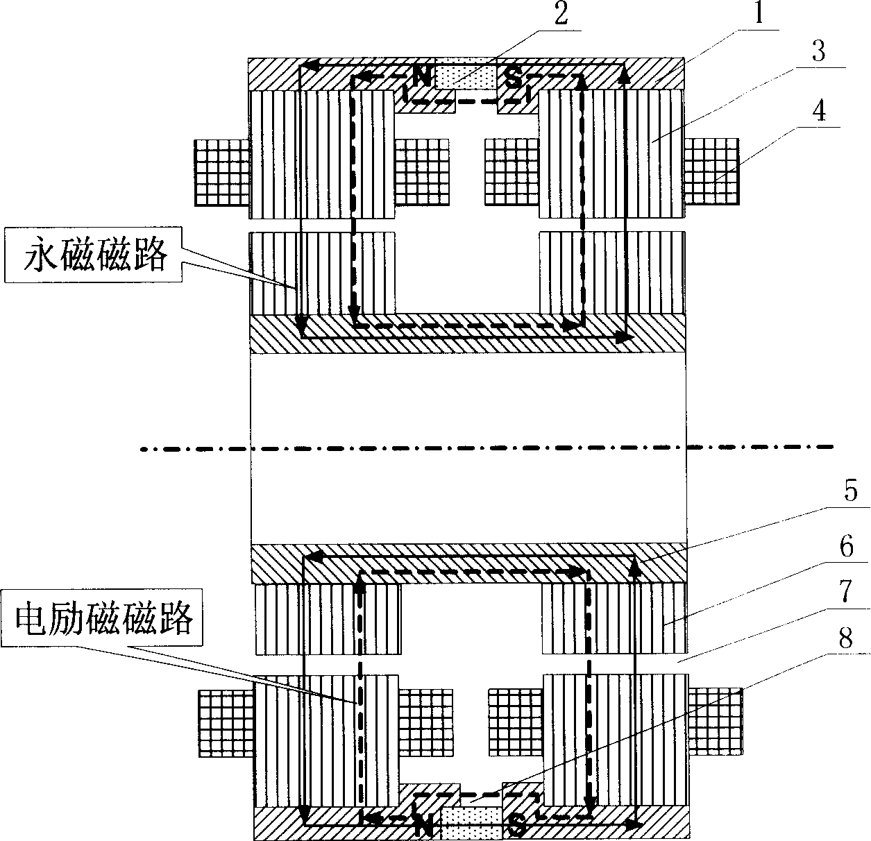
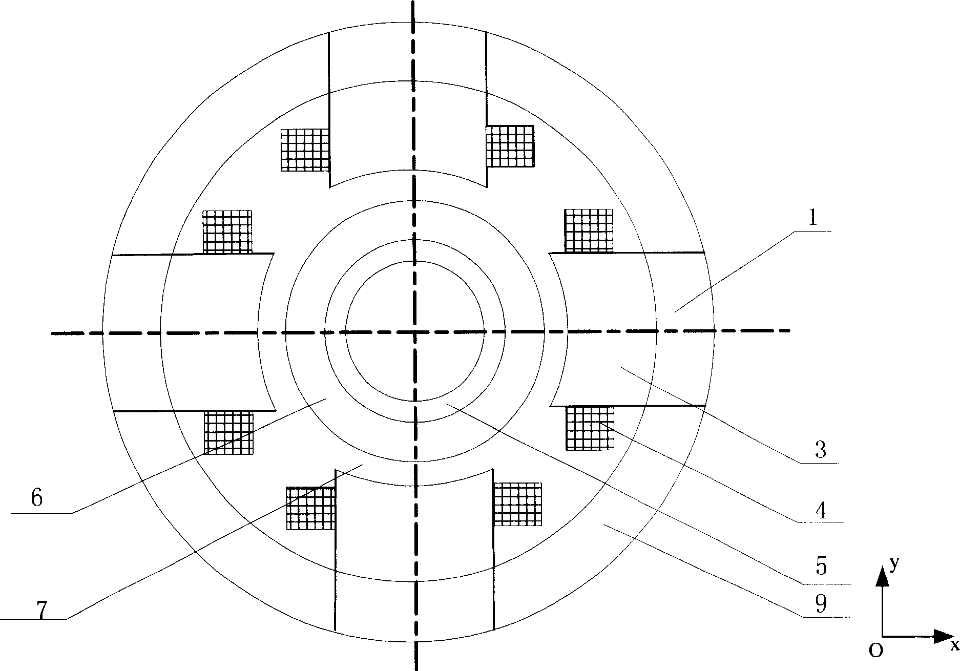
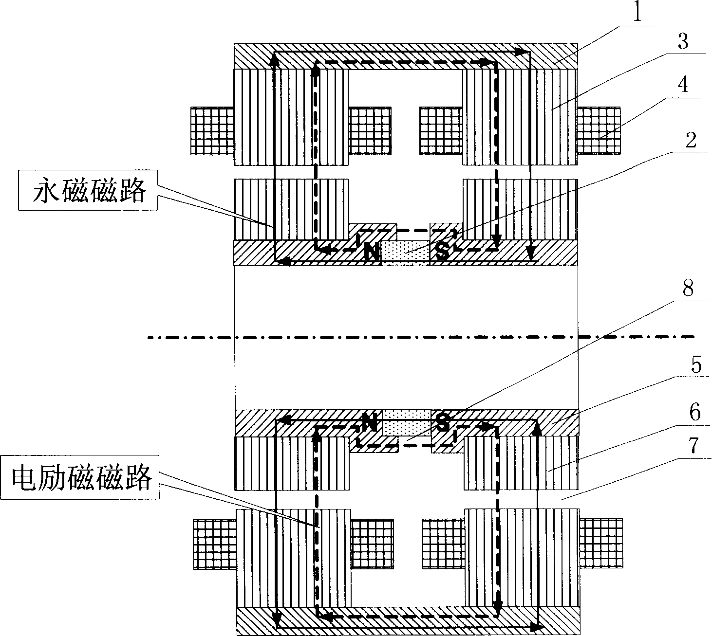
[0014] Such as figure 1 , 2 Shown, be the outer magnetic steel of one of technical solutions of the present invention, outer magnetic coil low power consumption permanent magnet bias inner rotor radial magnetic bearing, i.e. the basic form of the present invention, it consists of 2 outer magnetic rings 1, 1 permanent magnet 2, 2 stator cores 3, 8 excitation coils 4, 1 inner magnetic ring 5, 2 rotor cores 6, 8 air gaps 7, each stator core 3 consists of 4 magnetic poles, 2 A stator core 3 forms 8 magnetic poles at the left and right ends of the magnetic bearing, which respectively form the magnetic poles in the positive and negative directions of the X and Y axes. The magnetic ring 1 is connected with the stator core 3, the permanent magnet 2 is in the middle of the two outer magnetic rings 1, the inside of the stator core 3 is the rotor core 6, and there is a certain gap between the inner surface of the stator core 3 and the outer surface of the rotor core 6, An air gap 7 is ...


PUM


Abstract

The radial magnetic bearing consists of outer magnetizer, permanent magnet, stator iron core, exciting coil, inner magnetizer ring and rotor iron core. Each stator iron core constitutes four stator magnetic poles, and two stator iron cores constitute eight stator magnetic poles on two, right and left, ends of the magnetic bearing and in four, X, Y, -X and -Y, directions. Each of the stator magnetic poles has corresponding wound exciting coil, and the stator iron core has connected outer magnetizer rings, permanent magnet between two outer magnetizer rings, inside rotor iron core with air gap between the inner surface of the stator iron core and the outer surface of the rotor iron core, and inner magnetizer ring to connect the right and left ends of the rotor iron core to form magnetic path. The present invention has the advantages of low power consumption, small size, light weight, easy manufacture, etc. and may be used as the no-contact support for rotating part in machine.

Description

Technical field [0001] The invention relates to a non-contact magnetic suspension bearing, in particular to a low-power permanent magnet bias inner rotor radial magnetic bearing, which can be used as a non-contact support for rotating parts in mechanical equipment such as motors and machine tools. Background technique [0002] Magnetic suspension bearings are divided into pure electromagnetic bearings and hybrid magnetic suspension bearings with permanent magnetic bias and electromagnetic control. The former uses large current and consumes a lot of power, and the hybrid magnetic suspension bearings with permanent magnetic bias and electromagnetic control. The magnetic field generated by the permanent magnet bears the main load. Bearing capacity, the electromagnetic field provides auxiliary adjustment bearing capacity, so this kind of bearing can greatly reduce the control current and reduce the loss. However, some of the current permanent magnet bias inner rotor radial magne...

Claims


Application Information

Patent Timeline
Patent Type & Authority Patents(China)
IPC IPC(8): F16C32/04
Inventor 房建成马善振孙津济
Owner BEIHANG UNIV
Why Eureka
Try Eureka