4-Layer type of stator winding formed of sequentially connected segments located in respective slot pairs, and method of manufacture thereof

a stator winding and sequential connection technology, which is applied in the direction of windings, dynamo-electric components, and prefabricated windings. it can solve the problems of complex operation, difficult manufacturing, and substantial manufacturing difficulties of the stator winding, so as to achieve the effect of sequential manufacturing operations and convenient connection

Active Publication Date: 2005-11-24
DENSO CORP
View PDF4 Cites 55 Cited by
  • Summary
  • Abstract
  • Description
  • Claims
  • Application Information

AI Technical Summary

Benefits of technology

[0035] It is another advantage of the present invention that shaping of the leg ends of respective segments, in a stator winding as described above, can be readily performed. Specifically, to shape the conductors of a phase winding, each of the segments are first inserted with their legs in a straight condition, into a respective predetermined pairs of the stator slots, at respective predetermined layer positions, so that each leg will constitute the first, second, third or fourth conductor layer within a specific slot.
[0036] Each of the pairs of leg ends corresponding to the first and second conductor layers of each slot corresponding to that phase are then bent in a first circumferential direction, to displace respective tip portions of the leg ends by an amount substantially equal to one half of the pole pitch. Similarly, each of respective pairs of leg ends corresponding to the third and fourth conductor layers in each slot corresponding to that phase are bent in the opposite circumferential direction, to displace respective tip portions of the leg ends by an amount substantially equal to a half pole pitch. Respective pairs of leg ends corresponding to the first and second layers and corresponding to the third and fourth layers are thereby brought into proximity, and so can be readily connected, e.g., by welding.
[0037] Thus, the manufacturing operations to connect successive large / small segment pairs to form a phase winding can be simple.
[0038] According to another aspect, the invention provides a 4-layer sequential segment connection stator winding in which each phase winding is formed of at least one wave-wound coil that is formed of a succession of large / small segment pairs, but in which the large segments and small segment constitute a first segment group and a second segment group, with each large segment of the first segment group having its legs disposed as the first and fourth conductor layers respectively within a predetermined pair of stator slots (mutually separated by one pole pitch) and each small segment of the first segment group similarly having its legs disposed as the second and third conductor layers respectively within a predetermined pair of stator slots (mutually separated by one pole pitch). Similarly, each large segment of the second segment group has its disposed as the fifth and eighth conductor layers respectively within a predetermined pair of stator slots, and each small segment of the second segment group has its legs disposed as the sixth and seventh conductor layers respectively within a specific pair of stator slots. Each of the above-mentioned stator slots, of course, belong to the same phase.
[0039] In this case, each set of four leg ends corresponding to the first, second, third and fourth conductor layers of a stator slot are mutually connected and are connected to a set of four leg ends corresponding to the fifth, sixth, seventh and eighth conductor layers of a circumferentially adjacent identical-phase stator slot (i.e., which is distant by one pole pitch). In that way, the phase winding is formed as a single-turn wave-wound coil, that is made up of two wave-wound 1-turn coils that are connected in parallel (with each 1-turn coil formed of successive parallel-connected large / small segment pairs).
[0040] This configuration has the advantage of ease of manufacture, since, for each phase winding, shaping the segment leg ends (after the set legs have been inserted, in a straight condition, into the appropriate slot pairs at the appropriate layer positions) is performed simply by bending all of the leg ends protruding from the first to fourth conductor layers in one circumferential direction, such as to circumferentially move each tip portion of each leg end by an amount equal to one-half pole pitch, and to similarly bend all of the leg ends protruding from the fifth to eighth conductor layers by the same amount in the opposite direction. Respective pairs of sets of four tip portions of the leg ends are thereby oriented mutually adjacent, so that welding to connect these can be readily performed.

Problems solved by technology

However this has various disadvantages, such as the need to have a number of different types of segments, and complexity of establishing connections between the sets of six segment leg ends protruding from each slot, so that such a stator winding presents substantial manufacturing difficulties.
However with a type of 4-layer sequential segment connection stator winding that is described in or could readily be envisaged from the prior art, the arrangement of the leg ends of the segments, and operations to connect respective pairs of leg ends (e.g., by welding) is complex, so that manufacture is difficult.
Furthermore due to the fact that there be a substantial difference in potential between conductors that are located at adjacent layer positions within the same slot, it is necessary to pay careful attention to providing sufficient electrical insulation between such adjacent conductors within each slot, if the rotary electric machine is to operate with high levels of voltage being developed in (or applied to) the stator winding.
Hence, the manufacturing difficulty is further increased.
However such configurations having more than 4 layers per slot each have the disadvantages (in addition to those described hereinabove of a 4-layer sequential segment connection stator winding derived based on the prior art) that the axial length of the stator winding is increased, due to an increased degree of protrusion of the sequentially connected leg ends, and that it is necessary to use a greater number of different types of segment.

Method used


Image

  • 4-Layer type of stator winding formed of sequentially connected segments located in respective slot pairs, and method of manufacture thereof
  • 4-Layer type of stator winding formed of sequentially connected segments located in respective slot pairs, and method of manufacture thereof
  • 4-Layer type of stator winding formed of sequentially connected segments located in respective slot pairs, and method of manufacture thereof

Examples


first embodiment

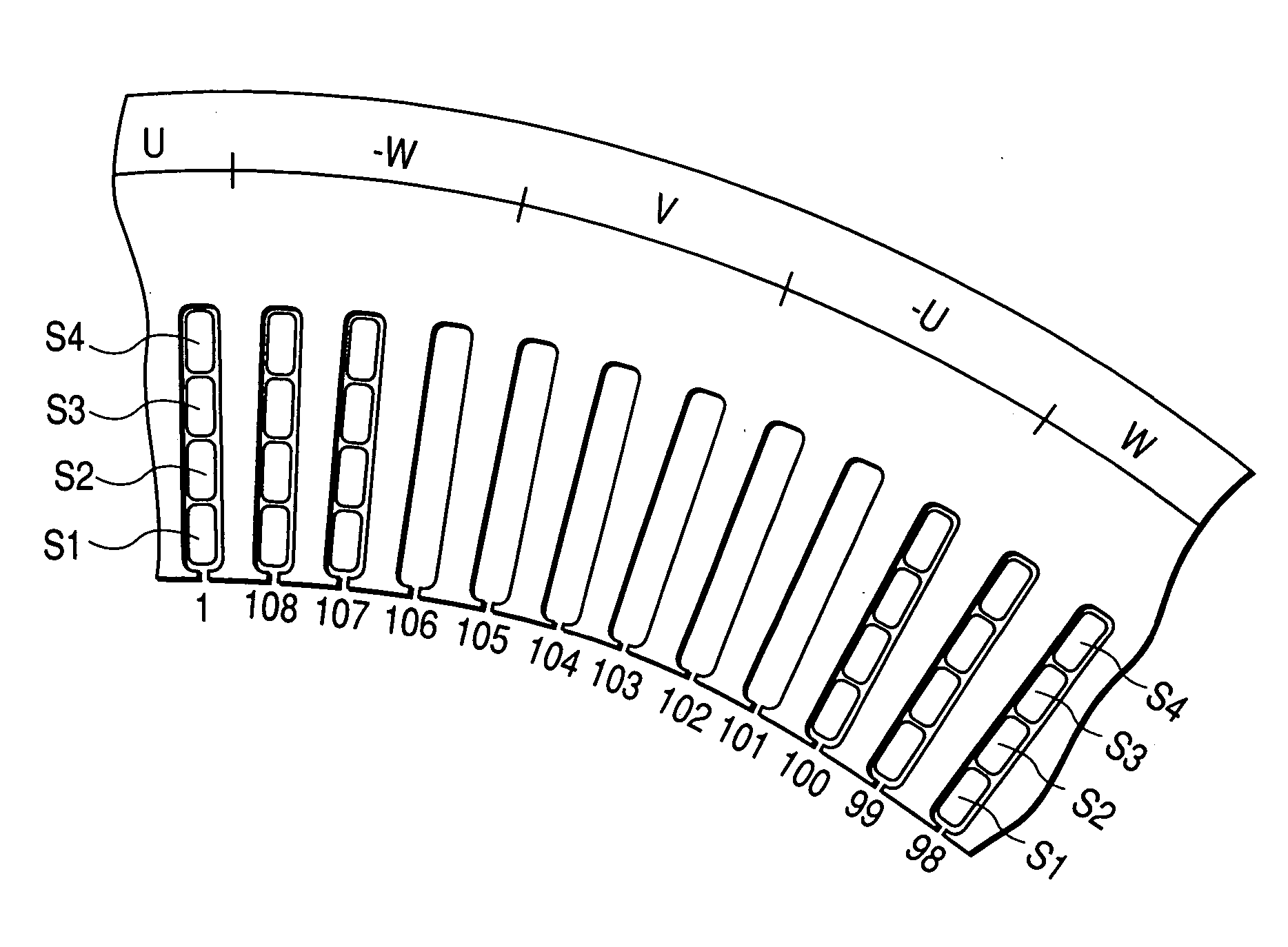
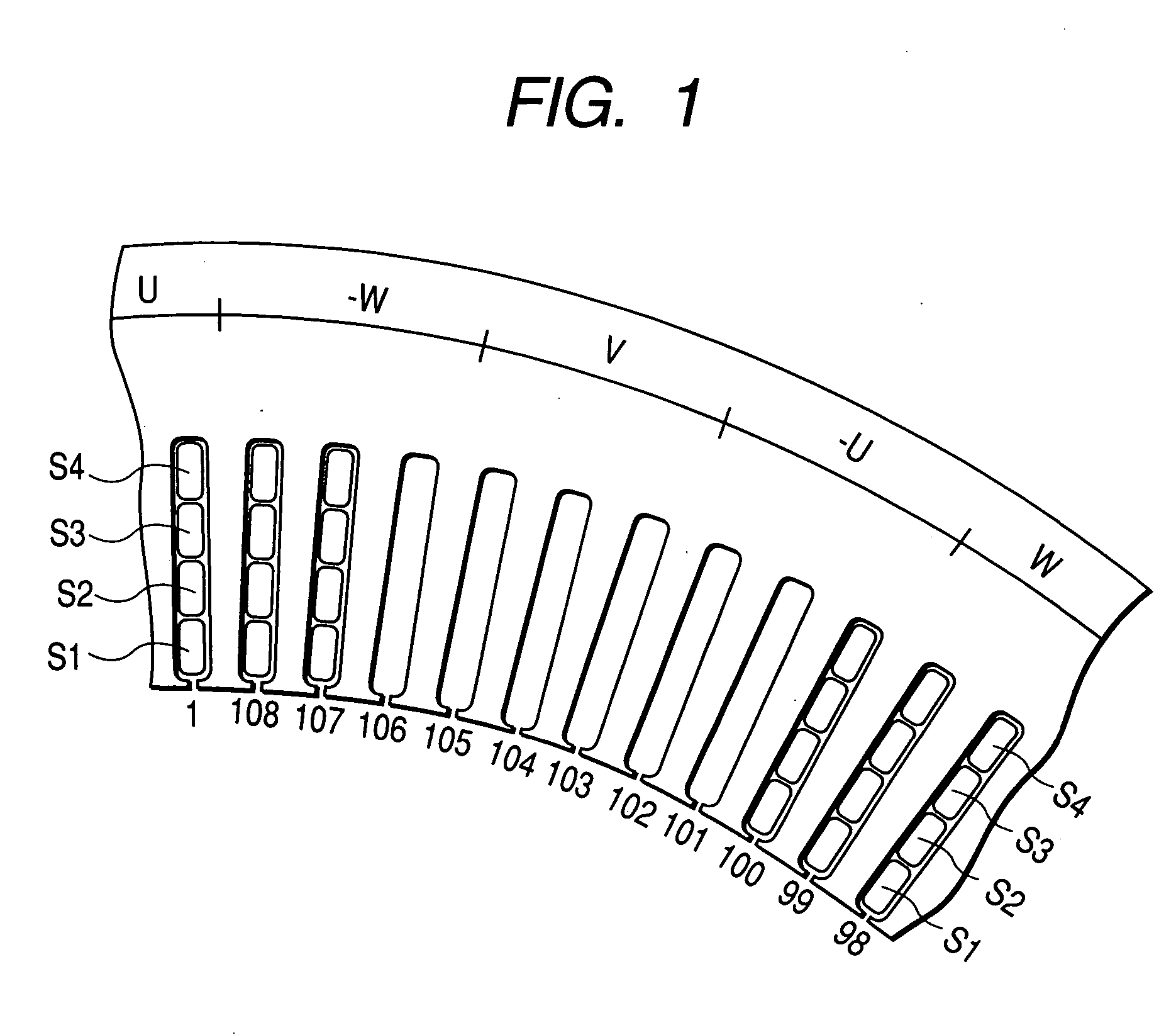
[0062]FIG. 1 is a partial view of a stator of a 3-phase 12-pole rotary electric machine, having a first embodiment of a stator winding formed thereon. As indicated, the stator core has a total of 108 slots, so that there are 9 slots per pole, so that the pole pitch is nine times the slot pitch and there are three slots per pole. In that way, there are 36 sets of 3 mutually adjacent identical-phase slots, such as the slots 106 to 108. Such a set will be referred to in the following as an identical-phase 3-slot set.

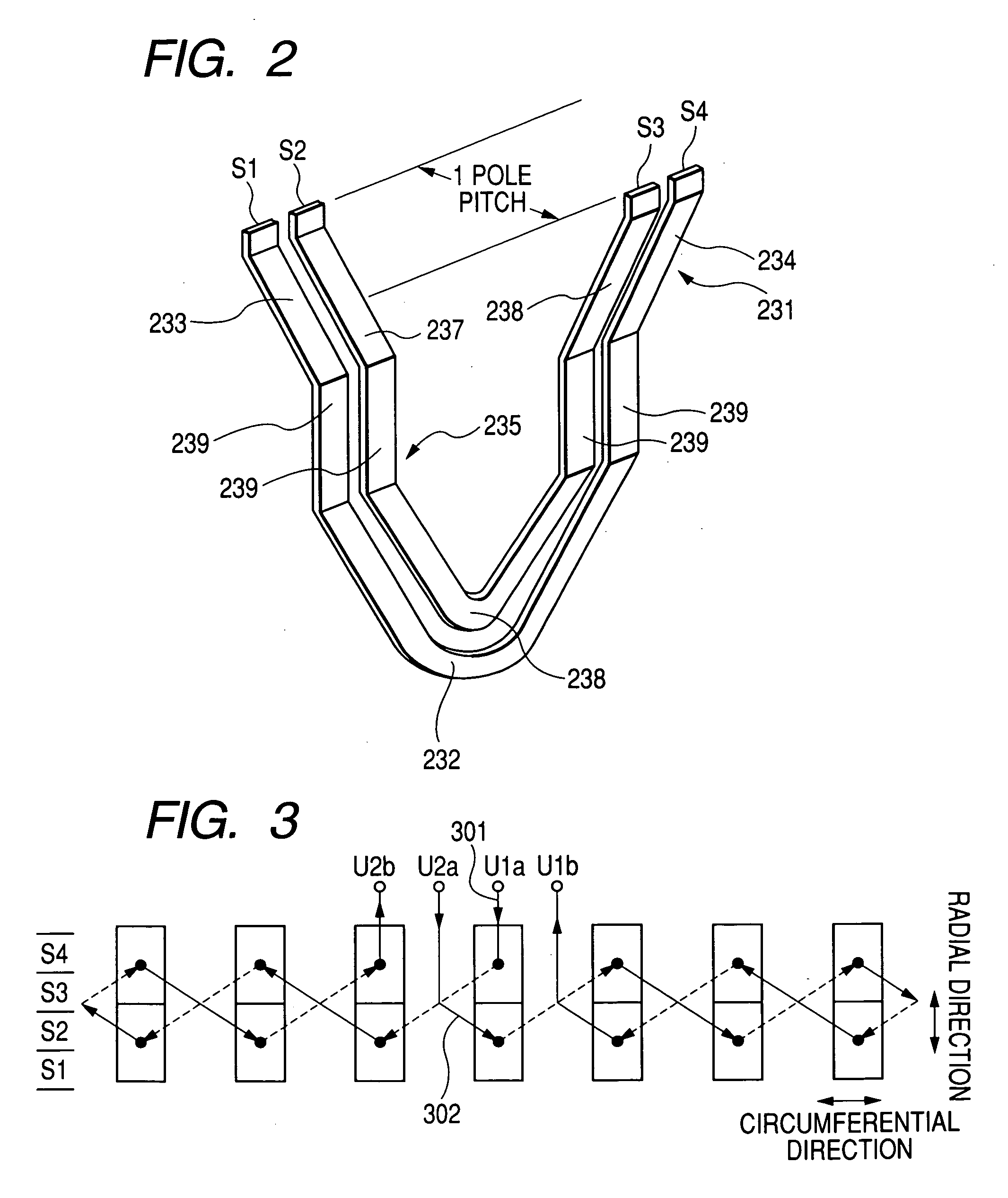
[0063] In each slot, there are four layers S1, S2, S4, S3 at successive radial positions (referred to as the first, second, third and fourth conductor layers in the following) as shown, with conductor each layer consisting of a single intra-slot portion of a segment, and layer S4 being the outermost layer.

[0064] Each of the segment intra-slot portions is covered with a thin layer of electrical insulation material.

[0065] This embodiment utilizes two forms of segment, whos...

second embodiment

[0089] A second embodiment will be described in the following, referring to the conceptual partial wiring diagram of FIG. 6. The first embodiment was described assuming that each identical-phase slot set consists of 3 adjacent slots, so that the pole pitch is nine times the slot pitch. With the second embodiment, each identical-phase slot set consists of two adjacent slots, so that the pole pitch is 6 times the slot pitch, and hence each parallel pair of a large segment and small segment extends between two slots that are spaced apart by 6 times the slot pitch.

[0090] As described for the first embodiment, the layers S1, S2 of a slot contain respective conductors of one partial coil, while the layers S3, S4 of the slot contain respective conductors of a second partial coil, with these partial coils being of the same phase. Hence, with the second embodiment, the two slots of each identical-phase slot set contain conductors of a total of four partial coils which are of the same phase....

third embodiment

[0100] A third embodiment of a 4-layer sequential segment connection stator winding for a 3-phase rotary electric machine will be described referring to the conceptual partial wiring diagram of FIG. 7. With this embodiment, each identical-phase slot set consists of a single slot, i.e., the pole pitch is three times the slot pitch, so that each parallel pair of large and small segments 231, 235 extends between two slots that are spaced apart by three times the slot pitch. In addition, this embodiment differs from the previous embodiments in that there are 8 layer positions within each slot, with the successively radially extending layers designated as S1 to S8 respectively as shown in FIG. 7.

[0101] The conductors of the four layers S1 to S4 are connected to constitute a first pair of partial coils (referred to in the following as the radially inward-side partial coils) in the same way as described for the first embodiment, while the conductors of the four layers S5 to S8 are similar...


PUM

PropertyMeasurementUnit
distanceaaaaaaaaaa
sizesaaaaaaaaaa
sizeaaaaaaaaaa

Abstract

A phase winding of a stator winding comprises one or more pairs of interconnected partial coil, each partial coil formed of sequentially connected U-shaped segment pairs, each pair comprising a large segment and small segment. Two segment legs, of the large and small segment respectively of such a pair, constitute first and second conductor layers of a first stator slot and have their tip portions mutually connected. The remaining two segment legs respectively constitute fourth and third conductor layers of a second slot that is distant by one pole pitch, and have their respective tip portions mutually connected.

Description

[0001] This application is based on and incorporates herein by reference Japanese Patent Application No. 2004-153561 filed on May 24, 2004. BACKGROUND OF THE INVENTION [0002] 1. Field of Application [0003] The present invention relates to a 4-layer type of stator winding for a rotary electric machine, with the stator winding formed of respectively separate U-shaped segments, and with the ends of leg portions of the segments sequentially connected after the segments have been inserted within respective pairs of stator slots. [0004] 2. Description of the Prior Art [0005] In the prior art, types of rotary electric machines such as 3-phase alternators for motor vehicles have been proposed, in which the armature winding (assumed in the following to be a stator winding) has a multi-layer configuration, formed of a plurality of pre-formed U-shaped winding segments (sometimes referred to as “hairpin conductors”}. The legs of each segment are inserted into a pair of slots of the stator, such...

Claims


Application Information

Patent Timeline
Patent Type & Authority Applications(United States)
IPC IPC(8): H02K3/04H02K1/00H02K3/12H02K3/28H02K3/34H02K15/06
CPCH02K3/12Y10T29/49009H02K3/28
Inventor KOUDA, SHINJISEGUCHI, MASAHIRO
Owner DENSO CORP
Why Eureka
Try Eureka