High light load efficiency synchronous buck regulator with pulse skipping control

a synchronous buck regulator and high light load efficiency technology, applied in the field of voltage regulators, can solve the problems of low light load efficiency of traditional synchronous buck converters, high switching losses, and design that does not provide improvement for both switching and conduction losses, so as to achieve the effect of reducing conduction losses and switching losses

Inactive Publication Date: 2005-11-24
INTERSIL INC
View PDF20 Cites 52 Cited by
  • Summary
  • Abstract
  • Description
  • Claims
  • Application Information

AI Technical Summary

Benefits of technology

[0003] The present invention overcomes the foregoing and other problems with a voltage regulator including the voltage source for providing an input voltage. The voltage regulator further includes associated circuitry for regulating the input voltage to provide an output voltage. The associated circuitry includes at least a high side switch and a low side switch. A skip mode controller controls the high side switch and low switch to minimize the conduction losses and the switching losses within the voltage regulator.

Problems solved by technology

The voltage waveform across the switches at the output is square wave in nature and generally results in higher switching losses when the switching frequency is increased.
Traditional synchronous buck converters suffer from low light load efficiencies due to the high switching losses and high conduction losses created by the circuit.
While circuitries have been developed for controlling the high conduction losses within traditional synchronous buck converters, there has been no design that provides improvement for both switching and conduction losses and provides for smooth transitions between the discontinuous current mode and continuous current mode of operation of the converter.

Method used


Image

  • High light load efficiency synchronous buck regulator with pulse skipping control
  • High light load efficiency synchronous buck regulator with pulse skipping control
  • High light load efficiency synchronous buck regulator with pulse skipping control

Examples


Embodiment Construction

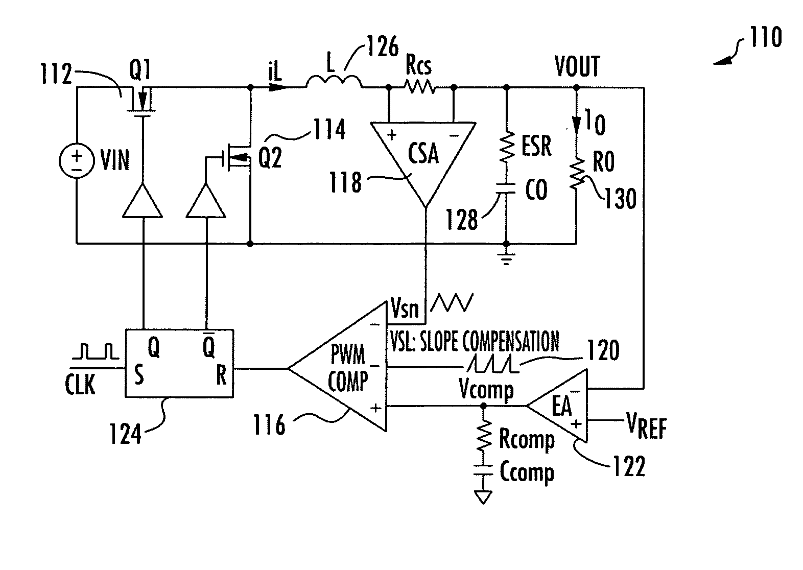
[0015] Referring now to the drawings, and more particularly to FIG. 1, there is illustrated a synchronous buck generator 110 including traditional constant frequency peak current mode control. The high side switch 112 and low side switch 114 are controlled complementarily from the outputs of the RS flip flop 124. A PWM comparator 116 compares the integrated voltage feedback signal VCOMP which is applied to the positive input of the PWM comparator 116 with the sum of the amplified current-sense signal from the current-sense amplifier 118 and a slope compensation ramp signal 120. The output of the PWM comparator 116 is applied to RS flip-flop 124, at each rising clock edge, the high side switch 112, consisting of a MOSFET transistor, is turned on until the sum of the amplified current signal from the current signal amplifier 118 and the slope compensation signal 120 is greater than the integrated voltage feedback signal from the error amplifier 122. When this signal condition is reach...


PUM


Abstract

A voltage regulator includes a voltage source for providing an input voltage and circuitry for regulating the input voltage to provide an output voltage. The circuitry for regulating the input voltage includes at least a high side switch and a low side switch. A skip mode controller controls the high side switch and the low side switch in order to minimize conduction losses and switching losses within the voltage regulator.

Description

TECHNICAL FIELD OF THE INVENTION [0001] The present invention relates to voltage regulators, and more particularly, to system and method for improving switching losses within a voltage regulator. BACKGROUND OF THE INVENTION [0002] A buck regulator is a switching power supply including at least one series switching transistor that chops the input voltage and applies the pulses to an average inductive capacitive filter. The output voltage of a buck regulator is lower than the input voltage. Buck regulators are one type of pulse width modulated (PWM) converters which are switching power supplies using power semiconductor switches in the on and off switching states to provide a device with high efficiency, small size and light weight. Pulse width modulated converters employ square wave pulse width modulation to achieve voltage regulation. The output voltage of the PWM converter is varied by varying the duty cycle of the power semiconductor switches within the circuit. The voltage wavefo...

Claims


Application Information

Patent Timeline
Patent Type & Authority Applications(United States)
IPC IPC(8): G05F1/40H02M3/158
CPCY02B70/1466H02M3/1588Y02B70/10
Inventor CHEN, JOSONQIAN, JINRONGSHEN, SISAN
Owner INTERSIL INC
Why Eureka
Try Eureka