Apparatus and method for the determination of a direction of an object

Inactive Publication Date: 2005-11-24
INFINEON TECH AG
View PDF7 Cites 82 Cited by
  • Summary
  • Abstract
  • Description
  • Claims
  • Application Information

AI Technical Summary

Benefits of technology

[0015] Starting from this prior art, it is an object of the present invention to provide an improved concept for the determination of the relative direction of an indicator object, this concept being particularly insens

Problems solved by technology

In this procedure known in the prior art for sensing the movement or rotational direction of an indicator object, it is, however, disadvantageous that a stationary background signal (backbias signal), such as the field of a permanent magnet, is not canceled in the rotational speed recognition by means of magnetic field sensors.
Moreover, it is disadvantageous in this procedure that the synchronism (matching) of the two magnetic field sensor elements (12, 14) has to be very good so that the offset difference of the output waveforms of both magnetic field sensor elements 12, 14 becomes small, in order to obtain reasonable measurement results.
The evaluation of this differential signal may however by very intensive due to overshoots in the waveform, because the output signal of t

Method used


Image

  • Apparatus and method for the determination of a direction of an object
  • Apparatus and method for the determination of a direction of an object
  • Apparatus and method for the determination of a direction of an object

Examples


Embodiment Construction

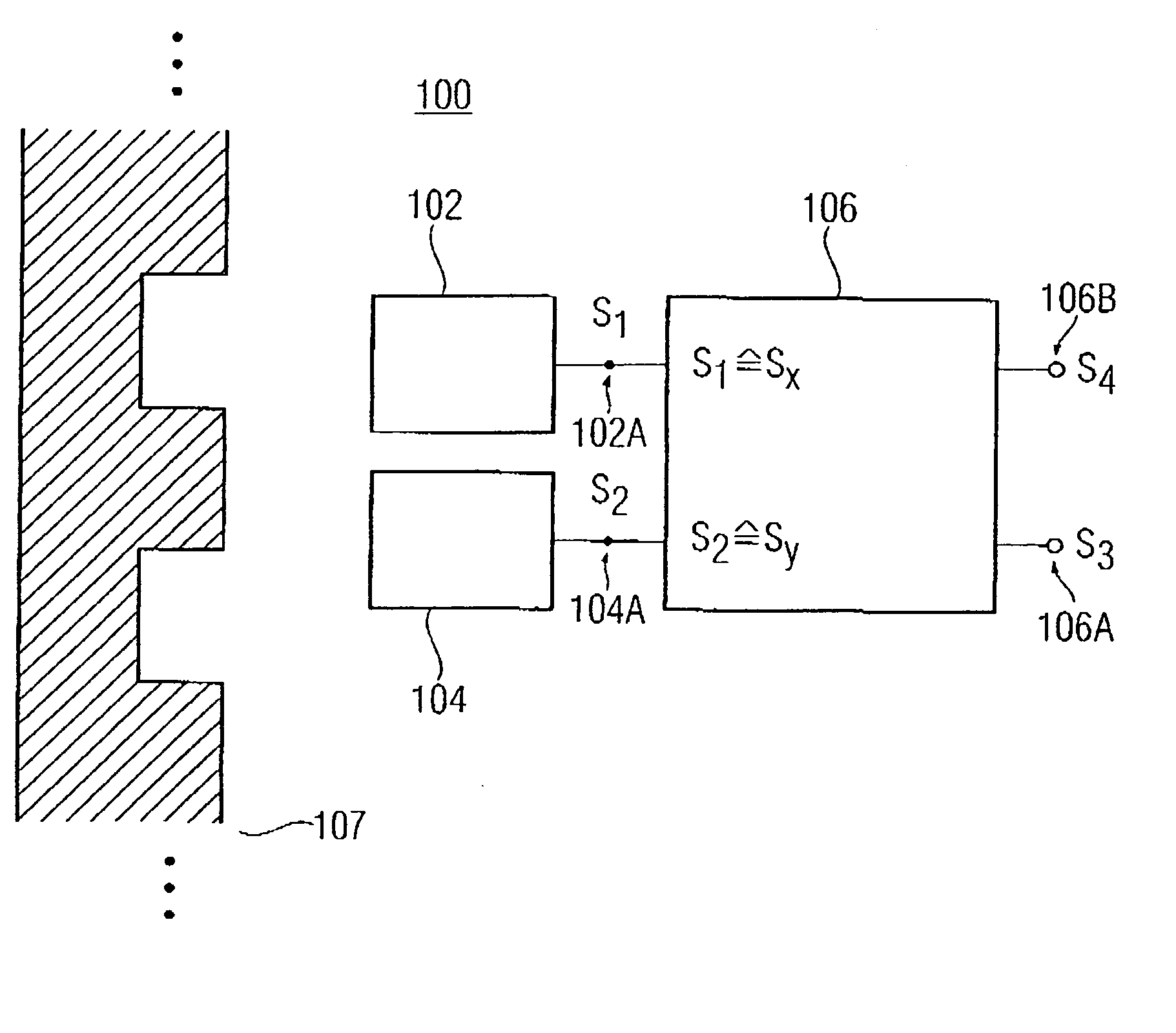
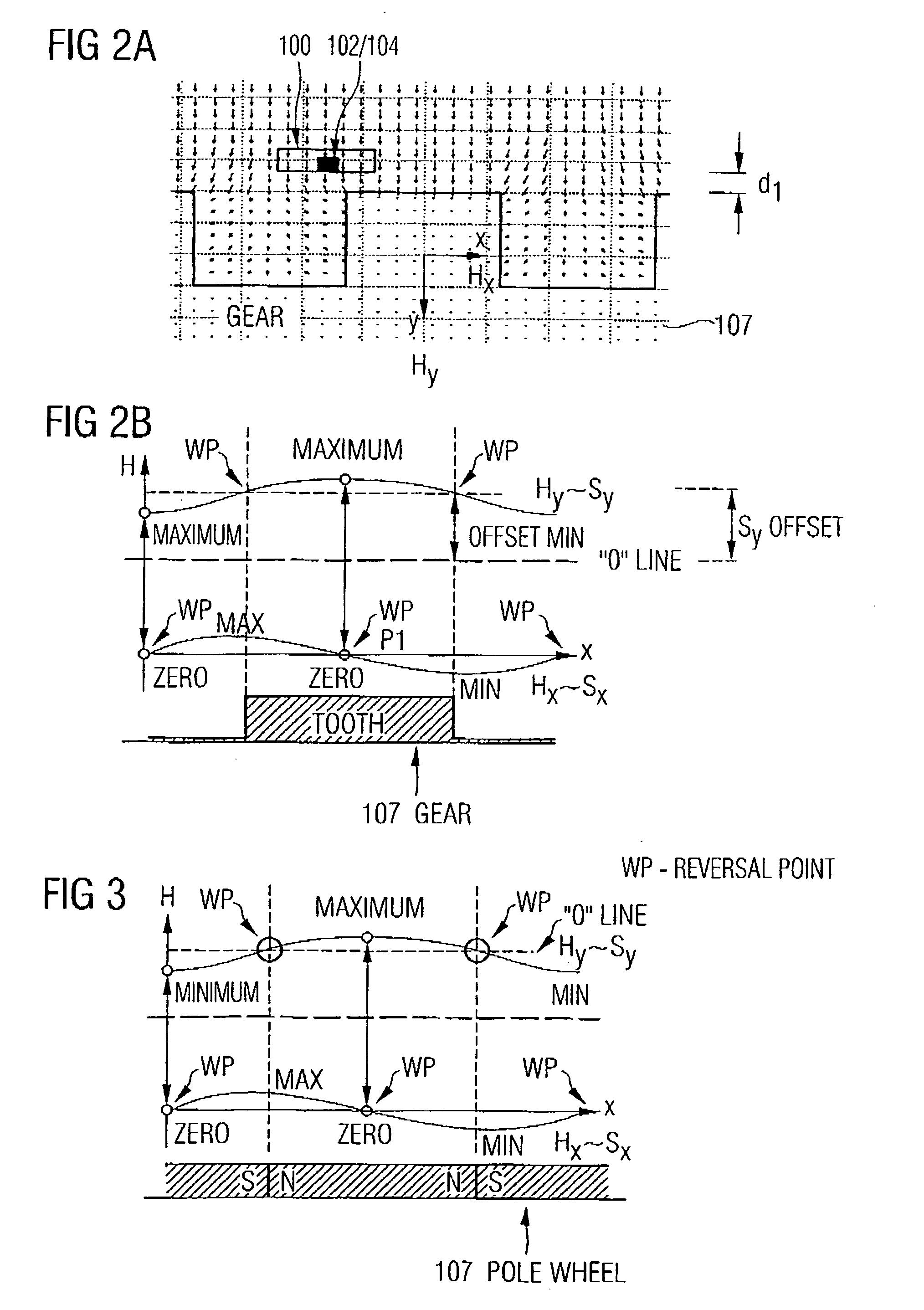
[0041] With reference to FIGS. 1, 2a-b, 3, now a first inventive embodiment of an apparatus 100 for the determination of a momentary relative direction of an indicator object is described. Generally, each item of ferromagnetic or permanent magnetic material influencing the present magnetic field in its environment or generating a corresponding magnetic field is to be regarded as indicator object.

[0042] According to the present invention, it is further to be noted that the inventive apparatus and the inventive method for the determination of a direction of an indicator object can be preferably employed in applications in which a magnetic field is used for the detection of velocity or rotational speed and direction or rotational directions of an indicator object. According to the invention, so-called gears or gear racks may thus be employed as indicator objects in connection with a backbias magnet, with the backbias magnet generating a background magnetic field defined or influenced ...


PUM


Abstract

An apparatus for the determination of a momentary relative direction of an indicator object depending on a magnetic field influenced or generated by the indicator object includes first means for sensing a course of a first magnetic field component of the magnetic field, second means for sensing a course of a second magnetic field component of the magnetic field, and means for evaluating the course of the first magnetic field component and the second magnetic field component in order to determine the momentary, relative direction of the indicator object, the first magnetic field component and the second magnetic field component being offset in angle with respect to each other.

Description

PRIORITY [0001] This application claims priority from German Patent Application No. 102004017191.2, which was filed on Apr. 07, 2004, and is incorporated herein by reference in its entirety. TECHNICAL FIELD OF THE INVENTION [0002] The present invention generally relates to an apparatus and a method for the determination of a relative direction of an object or indicator object or giver object, and in particular to the determination of a relative rotational direction or direction of movement of an indicator object, such as a rotating wheel, by means of magnetic field sensing elements arranged relative to the movement or rotational direction of the indicator object. DESCRIPTION OF RELATED ART AND BACKGROUND OF THE INVENTION [0003] In numerous applications, apart from rotational speed or velocity measurements of an indicator object, often also the recognition of the direction of movement or rotational direction of the indicator object, such as the rotational direction of a wheel or a sh...

Claims


Application Information

Patent Timeline
IPC IPC(8): G01D5/14G01D5/245G01P3/488G01P3/489G01P13/04G01R1/20G01R33/09
CPCG01D5/145G01D5/147G01P13/04G01P3/488G01D5/2451
Inventor FORSTER, BERNHARD
Owner INFINEON TECH AG
Why Eureka
Try Eureka