
Device, method and computer program for freely selectable frequency shifts in the subband domain

a subband domain and frequency shift technology, applied in the field of audio signal processing, can solve the problems of weak bandwidth limitation, near lossless reproduction of media contents, and problems in digital computers when using fourier transforms, and achieve the effect of efficient spectrum replication

Active Publication Date: 2015-04-23
FRAUNHOFER GESELLSCHAFT ZUR FOERDERUNG DER ANGEWANDTEN FORSCHUNG EV
View PDF13 Cites 12 Cited by
  • Summary
  • Abstract
  • Description
  • Claims
  • Application Information

AI Technical Summary

Benefits of technology

The patent describes a way to improve video quality by extending the bandwidth of video signals. This is done by analyzing the signals in the frequency domain and adjusting them to make them sound better. This method helps to reduce the amount of noise in the video and makes it sound more natural. It can be implemented in real-time systems and improves the overall quality of the video.

Problems solved by technology

These reproduction systems are characterized by a nearly lossless reproduction of media contents.
In particular in the beginning of audio encoding, the efficiency of the methods was of high importance since storage and computing performance were available only to a very limited extent.
In the field of mobile communications and satellite transmission, the bandwidth is limited strongly.
In practice, problems occur in digital computers when using the Fourier transform.
The great disadvantages of DFT are the high calculating complexity and the redundancy contained in the spectrum.
Although there are efficient methods for calculating the DFT, i.e. FFT, the result will be a complex spectrum.
However, it is of disadvantage that the DCT spectrum cannot be transformed with regard to absolute value (or magnitude) and phase.
For a signal processing of long audio signals, it is not possible to transform the signal as a whole.
On the one hand, the calculating complexity here increases enormously since N2 calculating operations are necessitated also for calculating the DCT.
On the other hand, it is not possible to process the signal in real time since transmission of the entire data stream has to be waited for until the signal may be reconstructed.
Audio encoders which try to restore the higher frequencies of a signal have to face this problem.
Despite the existence of various ways of reducing the data rate by audio encoding, current audio encoders reach their limits when low bit rates are desired.
In particular the psycho-acoustic methods in this case produce undesired signal corruptions.
This may be seen in interfering artefacts, like missing heights, blurred transients or artificial hissing of the audio signal reproduced.
In many cases of application, however, only a limited transmission bandwidth is available.
This copying process causes, in particular with low cutoff frequencies, perceivable artefacts like roughness and undesired changes in timbre.
In this kind of bandwidth extension, problems arise with highly tonal signals of a highly distinct harmonic structure.
Even if the SBR method provides for techniques for tonal adaptation of the spectrum, these are not sufficient for restoring a destroyed harmonic structure.
These artefacts are very unpleasant for the listener.
For harmonic signals, such as, for example, a pitch pipe, SBR and equivalent bandwidth extension methods produce undesired artefacts, such as, for example, tonal roughness and unpleasant timbres, since the harmonic structure of the signal is not maintained completely.
For signals exhibiting a distinct harmonic structure, undesired artefacts, like roughness and changes in timbre, occur when applying SBR.
Of disadvantage is the fact that the distance between the sub-tones in the HF region changes with the expansion factor by spreading the spectrum, as can be seen in FIG. 33.
In addition, complicated calculations are necessitated for spreading the spectrum.
Of disadvantage with this method is calculating the single sideband modulation.
However, when the frequency shift is realized in the time domain, this may be very complex.
Realizing the shift in the subband domain of a subband audio encoder in contrast may result in the frequency resolution to be too coarse for the frequency shift needed.
However, the aliasing compensation property of the MDCT filter bank is affected or destroyed by this.
Even if this method is not able to cancel all the aliasing components occurring, it is sufficient to eliminate a few dominant spurious portions.
The signal is described sufficiently precisely in its spectral representation, nevertheless this information is not sufficient for replicating the spectrum using HSBE.

Method used


Image

  • Device, method and computer program for freely selectable frequency shifts in the subband domain
  • Device, method and computer program for freely selectable frequency shifts in the subband domain
  • Device, method and computer program for freely selectable frequency shifts in the subband domain

Examples


Embodiment Construction

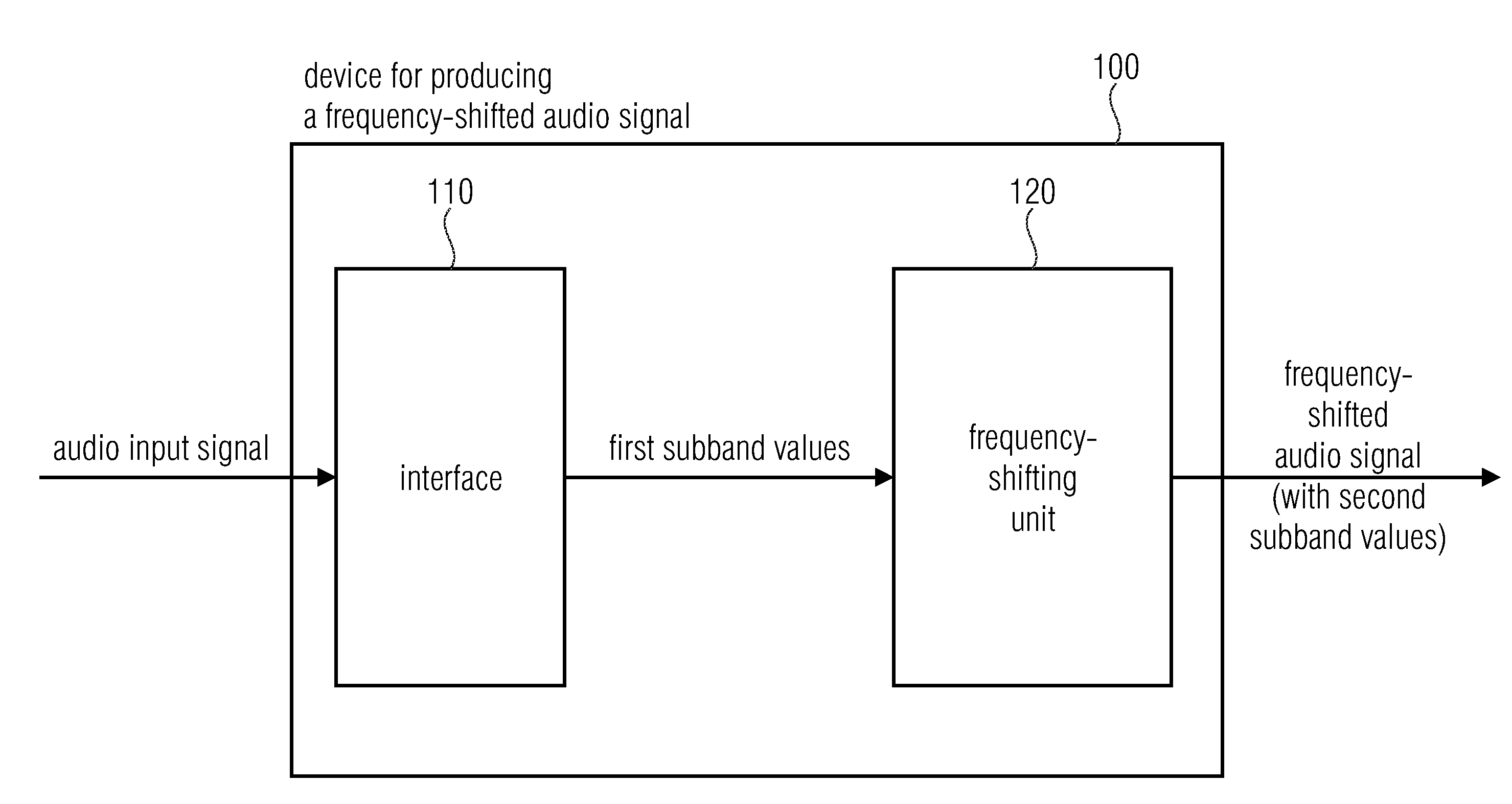
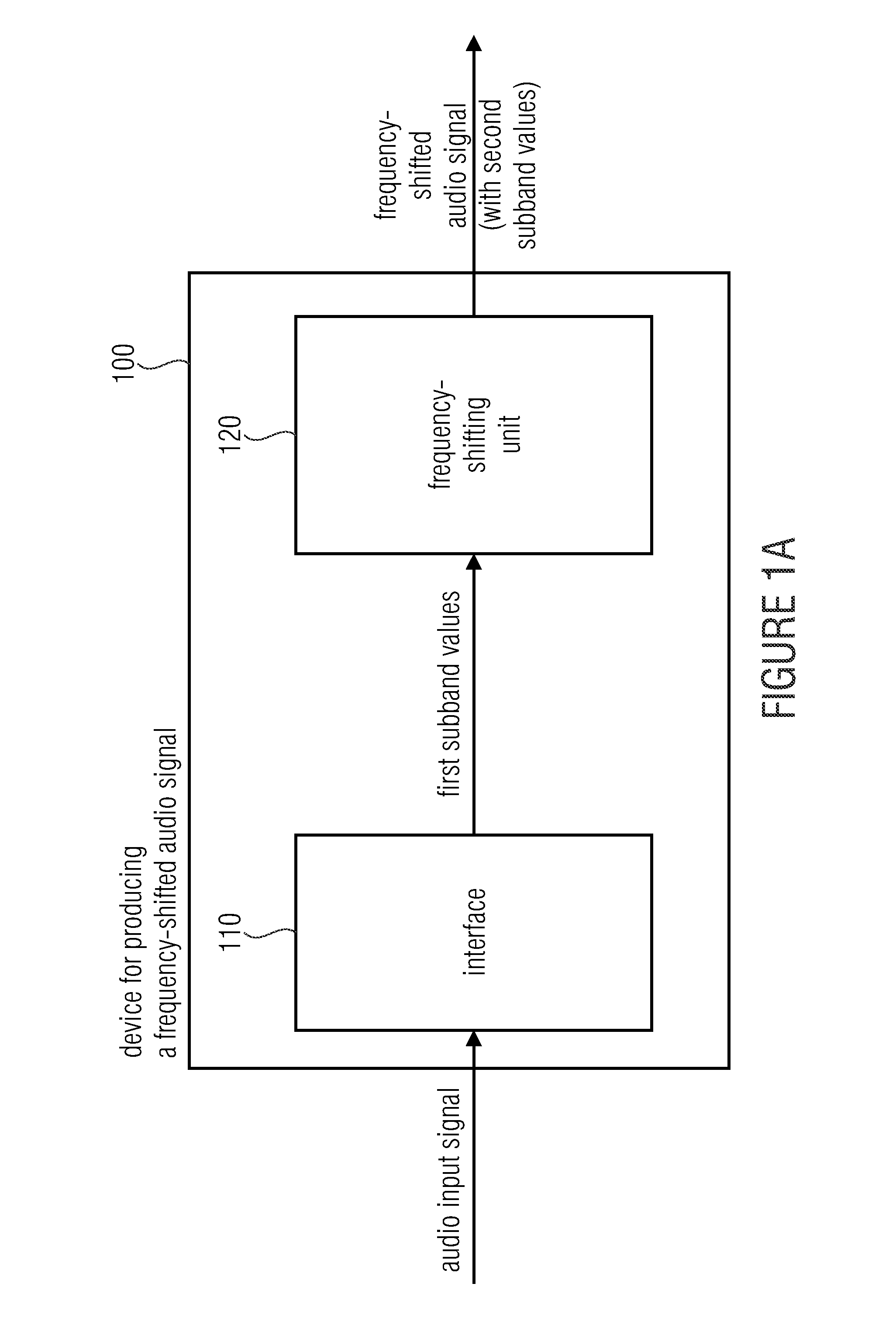
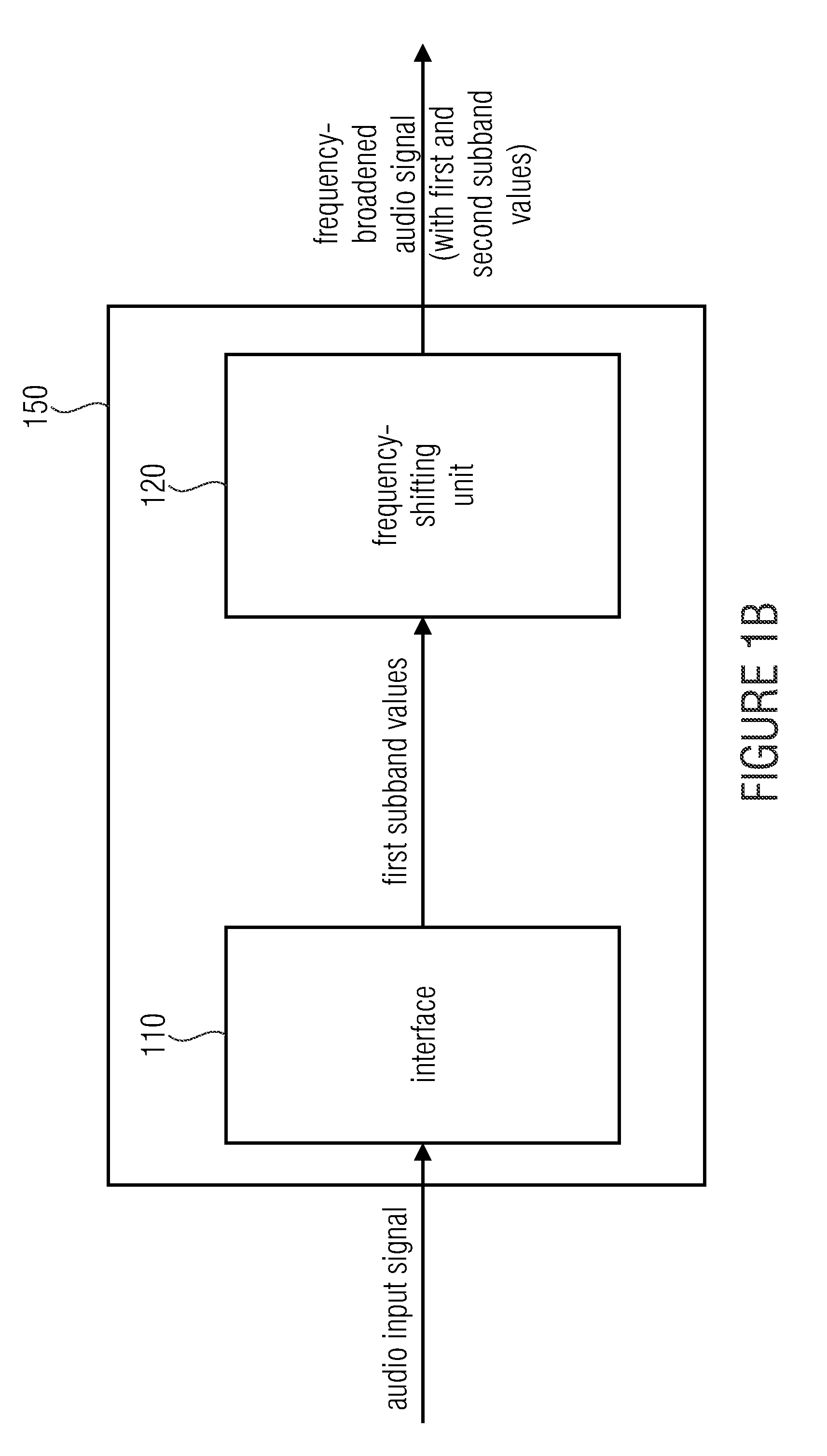
[0175]FIG. 1a shows a device 100 for producing a frequency-shifted audio signal based on an audio input signal. The audio input signal, for a plurality of first subbands, here may be represented by one or several first subband values. The device includes an interface 110 and a frequency-shifting unit 120. The interface 110 is configured for receiving the audio input signal. The frequency-shifting unit 120 is configured for producing the frequency-shifted audio signal, the frequency-shifted audio signal, for a plurality of second subbands, comprising one or several second subband values each. In addition, each of the first and second subband values comprises information on a respective phase angle. The frequency-shifting unit 120 is additionally configured to produce one of the second subband values based on one of the first subband values such that the second phase angle of this second subband value may differ from the first phase angle of this first subband value by a phase angle d...


PUM


Abstract

A device for producing a frequency-shifted audio signal based on an audio input signal is provided. The device has an interface and a frequency-shifting unit. The interface is configured for receiving the audio input signal. The frequency-shifting unit is configured for producing the frequency-shifted audio signal. The frequency-shifting unit is additionally configured to produce one of the second subband values based on one of the first subband values such that the second phase angle of this second subband value differs from the first phase angle of this first subband value by a phase angle difference, the phase angle difference being dependent on frequency information indicating by which frequency difference the audio input signal is to be shifted in order to obtain the frequency-shifted audio signal, and the phase angle difference being dependent on a frequency bandwidth of one of the first subbands.

Description

CROSS-REFERENCE TO RELATED APPLICATIONS[0001]This application is a continuation of copending International Application No. PCT / EP2013 / 063827, filed Jul. 1, 2013, which claims priority from U.S. Provisional Application No. 61 / 667,119, filed Jul. 2, 2012, and from European Application No. 12175808.0, filed Jul. 10, 2012, each of which are incorporated herein in its entirety by this reference thereto.BACKGROUND OF THE INVENTION[0002]The present invention relates to audio signal processing and, in particular, to a device, a method and a computer program for arbitrary frequency shifts in the subband domain.[0003]Computer-aided data processing systems are an integral part of everyday life in today's society which is characterized by new media. Systems for consuming new media have been present in nearly every household for quite some time. Examples of such systems which transmit and reproduce data in digital form are players for video and audio data, like, for example, for DVD and BluRay, ...

Claims


Application Information

Patent Timeline
Patent Type & Authority Applications(United States)
IPC IPC(8): G10L25/18H03G3/00G10L21/0388
CPCG10L25/18H03G3/00G10L21/0388G10L19/0204G10L19/02
Inventor NAGEL, FREDERIKSCHNABEL, MICHAELNEUKAM, CHRISTIANSCHULLER, GERALD
Owner FRAUNHOFER GESELLSCHAFT ZUR FOERDERUNG DER ANGEWANDTEN FORSCHUNG EV
Learn More