
Perpendicular magnetic recording head

a magnetic recording and perpendicular technology, applied in the field of perpendicular magnetic recording head, can solve the problems of ineffective inducing recording magnetic field, difficult to induce recording magnetic field in the front end of the main magnetic pole layer, so-called side fringing, etc., and achieve the effect of reducing the magnetic volume of the yoke layer and facilitating the induction of recording magnetic field

Active Publication Date: 2005-11-24
TDK CORPARATION
View PDF9 Cites 27 Cited by
  • Summary
  • Abstract
  • Description
  • Claims
  • Application Information

AI Technical Summary

Benefits of technology

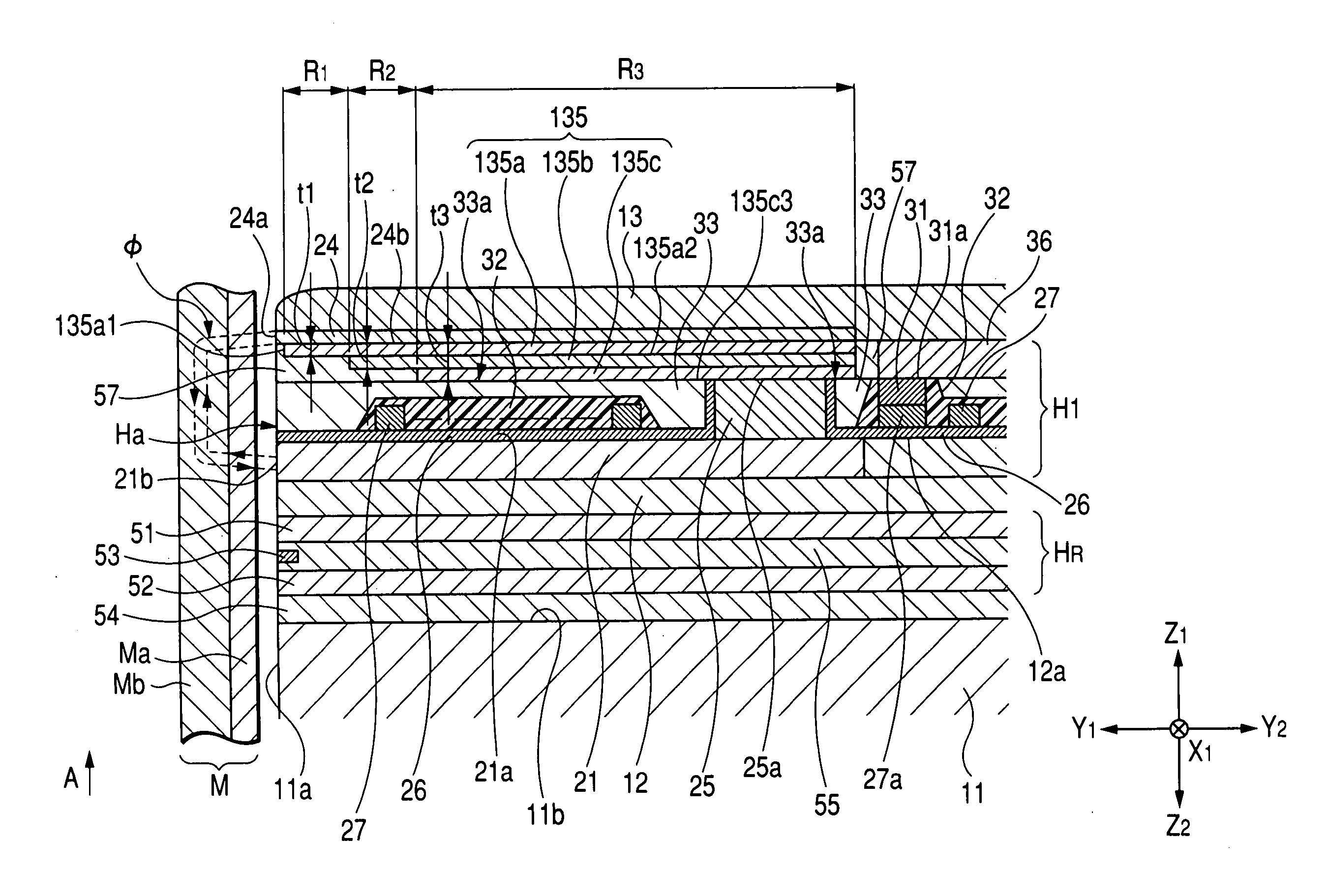
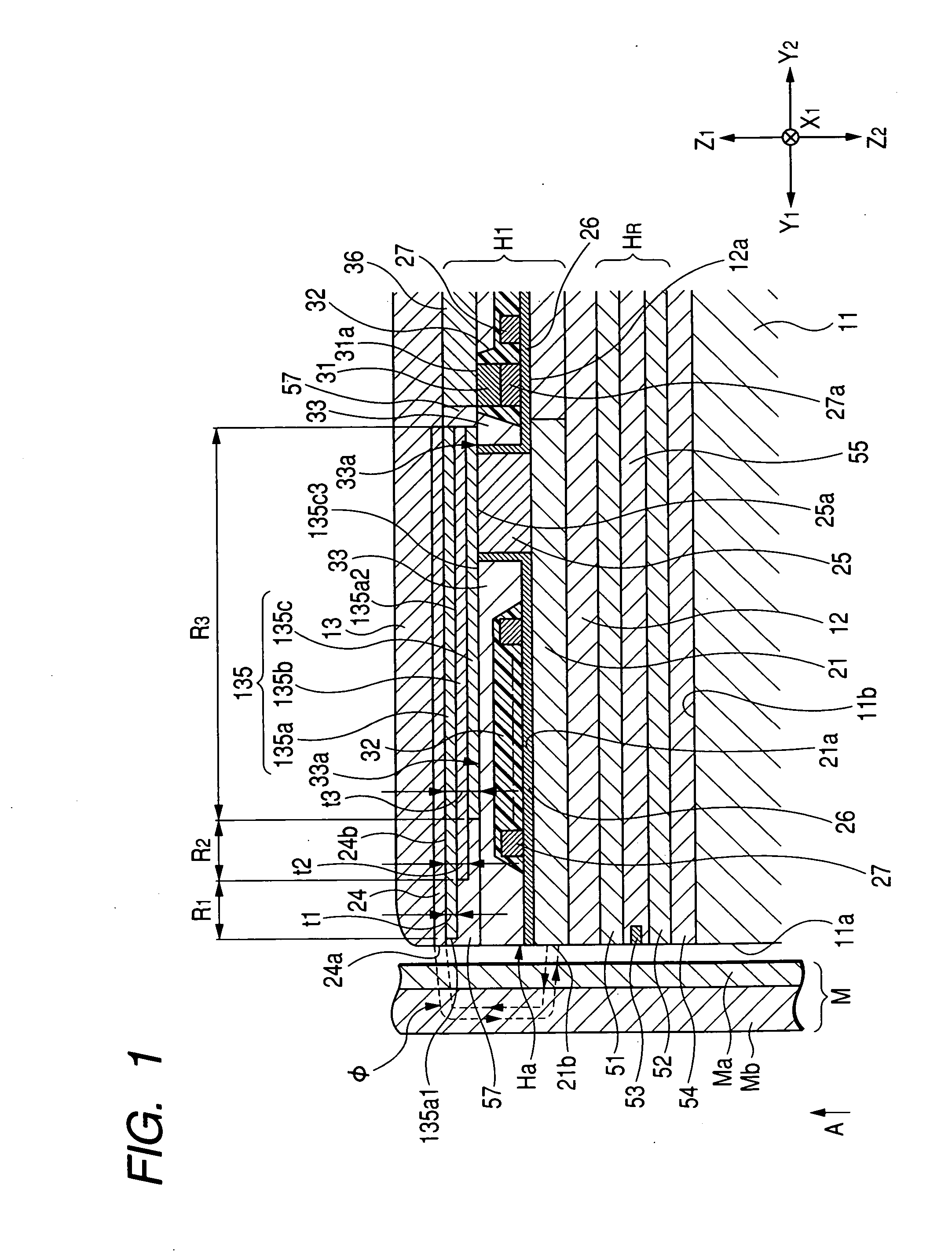
[0012] The present invention has been finalized in view of the drawbacks inherent in the conventional perpendicular magnetic recording head, and it is an object of the present invention to provide a perpendicular magnetic recording head capable of inducing a recording magnetic field in a front end portion of a main magnetic pole effectively, and preventing side fringing from being generated.
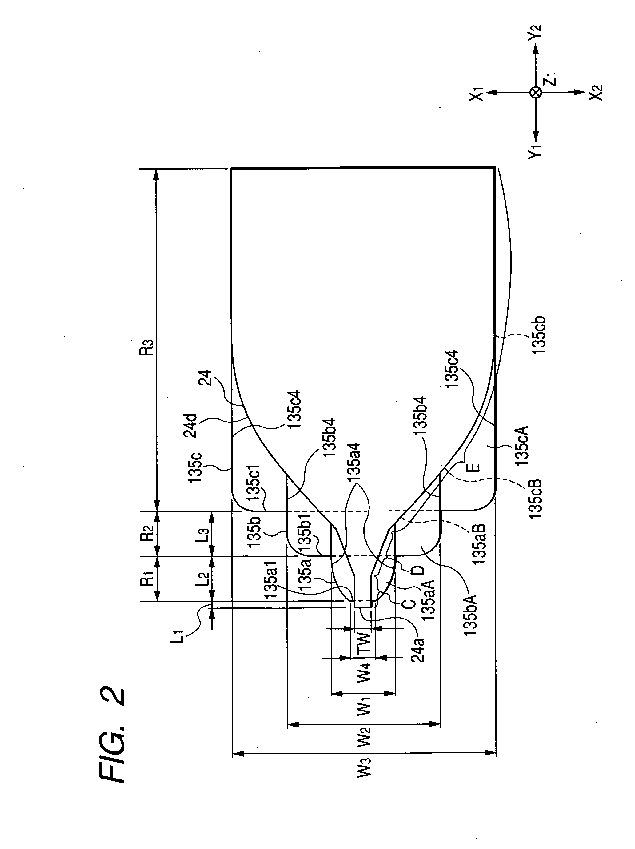
[0019] The width of the yoke layer is constructed to become larger as going in the height direction (in the Y2 direction in the drawing). The magnetic volume of the yoke layer becomes larger as going farther from the medium-opposing surface of the recording medium. Therefore, since it is possible to enlarge the magnetic volume of the yoke layer as a whole, the recording magnetic field can be easily induced in the main magnetic pole layer.

Problems solved by technology

However, since the ferromagnetic material has low permeability in general, it is difficult to induce the recording magnetic field induced in the main magnetic pole layer in the front end of the main magnetic pole layer.
As a result, there is a problem in that a so-called side fringing occurs.
Therefore, in the yoke layer 35 disclosed in Japanese Unexamined Patent Application Publication No. 2002-197615, since there is a limitation in increasing the magnetic volume as a whole, it is not possible to induce the recording magnetic field effectively in the main magnetic pole layer 24.

Method used


Image

  • Perpendicular magnetic recording head
  • Perpendicular magnetic recording head
  • Perpendicular magnetic recording head

Examples


example 1

[0231]FIG. 13 is a graph comparing a residual signal ratio of the embodiment with that of a comparative example. FIG. 14 is a graph comparing an output of the embodiment with that of the comparative example, FIG. 15 is a graph shown by standardizing the output at the time of saturated magnetization as 1 in the graph shown in FIG. 14. FIG. 16 is a graph showing the characteristics of overwriting in the embodiment and the comparative example. ‘OW(dB)’ of the longitudinal axis shown in FIG. 16 indicates ‘OW=20×log (signal intensity after overwriting / signal intensity before overwriting)’

[0232] Here, in the embodiment, the yoke layer composed of the first and second layers is formed below (in the Z2 direction in the drawing) the main magnetic pole layer 24 of the perpendicular magnetic recording head H5 shown in FIG. 17, and the auxiliary magnetic pole layer is formed above (in the Z1 direction in the drawing) the main magnetic pole layer 24. The front end surface of the first layer is p...


PUM


Abstract

A perpendicular magnetic recording head includes a first magnetic portion, a second magnetic portion formed with a gap from the first magnetic portion, and a coil layer located in the gap between the first magnetic portion and the second magnetic portion for applying a recording magnetic field to the first magnetic field and the second magnetic field. The yoke layer is formed on the second magnetic portion, a width whose direction is orthogonal to the height direction of a front end of the yoke layer becomes larger gradually or continuously as going in the height direction, and the width becomes larger gradually or continuously as going farther from the second magnetic portion.

Description

BACKGROUND OF THE INVENTION [0001] 1. Field of the Invention [0002] The present invention relates to a perpendicular magnetic recording head which performs recording by applying a vertical magnetic field to a recording medium, such as a disk having a hard surface, and more particularly, to a perpendicular magnetic recording head capable of suppressing the generation of fringing on a recording pattern and improving recording efficiency. [0003] 2. Description of the Related Art [0004] A perpendicular magnetic recording head has been used for a vertical magnetic recording system to record magnetic data on a recording medium, such as a disk, with high density. In general, this perpendicular magnetic recording head has the structure that it has an auxiliary magnetic pole layer made of ferromagnetic materials, and a main magnetic pole layer which is made of ferromagnetic materials and which is formed with a gap from the auxiliary magnetic pole layer. [0005] A front end of the auxiliary ma...

Claims


Application Information

Patent Timeline
IPC IPC(8): G11B5/127G11B5/147G11B5/31
CPCG11B5/1278G11B5/3146G11B5/3116
Inventor KAMEDA, HIROSHI
Owner TDK CORPARATION
Learn More