

Magnetic recording medium and method for producing the same
a technology of magnetic recording media and recording medium, which is applied in the direction of data recording, protective coatings of layers, instruments, etc., can solve the problems of increasing the risk of loss, the thickness of the magnetic layer, and the influence of loss, so as to improve the durability of the magnetic layer and improve the running performance of the tape. , the effect of improving the reliability of the magnetic recording medium
- Summary
- Abstract
- Description
- Claims
- Application Information
AI Technical Summary
Benefits of technology
Problems solved by technology
Method used
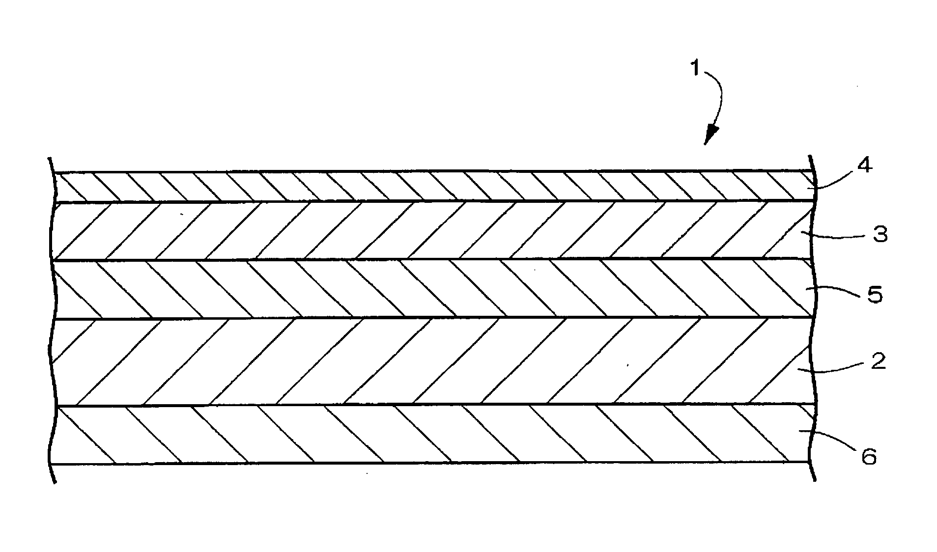
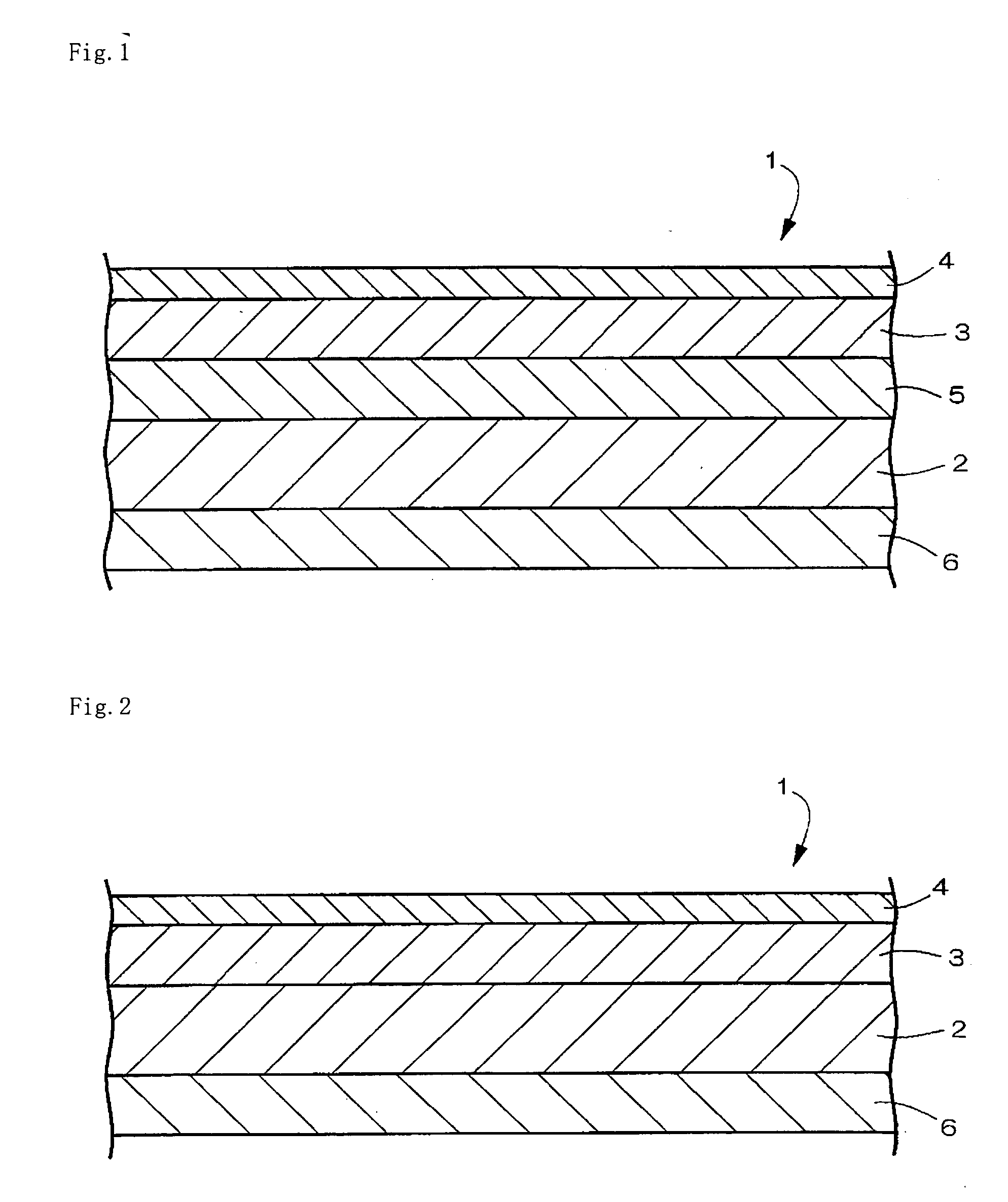
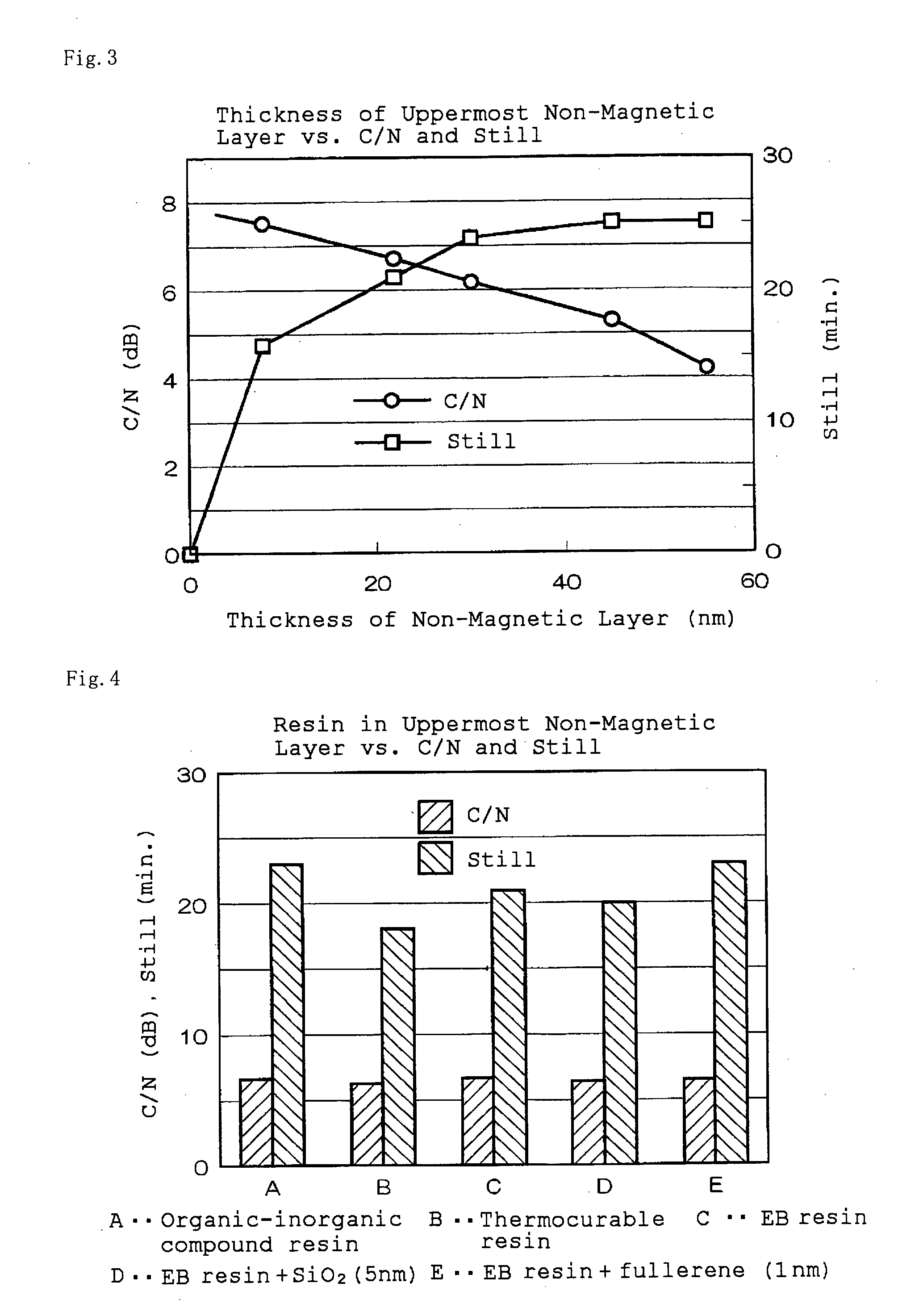
Image

Examples
example 1
[0119]
(1)Non-magnetic plate-shaped76partsiron oxide particleswith an average particlesize of 50 nmCarbon black with an24partsaverage particlesize of 25 nmStearic acid2.0partsVinyl chloride-hydroxypropyl8.8partsacrylate copolymercontaining a —SO3Nagroup (0.7 × 10⁻⁴ eq. / g)Polyester-polyurethane4.4partsresin which containsa —SO3Na group(1 × 10⁻⁴ eq. / g) and hasa Tg of. 40° C.Cyclohexanone25partsMethyl ethyl ketone40partsToluene10parts(2)Butyl stearate1partCyclohexanone70partsMethyl ethyl ketone50partsToluene20parts(3)Polyisocyanate1.4partsCyclohexanone10partsMethyl ethyl ketone15partsToluene10parts
(1) Kneading step
[0120] As the magnetic particles, iron nitride magnetic particles prepared as follows were used.
[0121] Iron sulfate (II) heptahydrate (41.9 mol) and iron nitride (III) enneahydrate (97.4 mol) were dissolved in water (150 kg). Next, sodium hydroxide (376 mol) was dissolved in water (150 kg). To the aqueous solution of the two different iron salts was added the aqueous sodium...
example 2
[0134] A computer tape of Example 2 was made in the same manner as in Example 1, except that magnetic particles (Co—Fe—Al—Y) (Co / Fe: 24 at. %, Al / (Fe+Co): 4.7 wt. %, Y / (Fe+Co): Co): 7.9 at. %, σs:119 Am2 / kg (119 emu / g), Hc: 181.4 kA / m (2280 Oe), average particle size: 60 nm, and axial ratio: 5) were used instead of the iron nitride magnetic particles (Y—Fe—N) (σs: 135.2 Am2 / kg (135.2 emu / g), Hc: 226.9 kA / m (2850 Oe), average particle size: 20 nm, and axial ratio: 1.1), and that the thickness of the magnetic layer was changed from 0.04 μm (40 nm) to 0.06 μm (60 nm).
example 3
[0135] A computer tape of Example 3 was made in the same manner as in Example 2, except for the following: 1.4 parts of polyisocyanate out of the components of the coating composition for the primer layer of Example 2 was changed to 1.4 parts of dipentaerythritol hexaacrylate; 1.5 parts of polyisocyanate out of the components of the coating composition for the magnetic layer was changed to 1.5 parts of dipentaerithritol hexaacrylate; 15 parts of polyisocyanate out of the components of the coating composition for the back layer was changed to 15 parts of dipentaerythritol hexaacrylate; and the components of the coacting composition for the non-magnetic layer were changed as follows.
Dipentaerythritol hexaacrylate40partsMethyl ethyl ketone60parts
[0136] Further, the final thickness of the primer layer was changed from 0.4 μm to 1.2 μm; the thickness of the magnetic layer, from 0.04 μm to 0.06 μm; and the thickness of the non-magnetic layer, from 8 nm to 22 nm, and these layers were ap...
PUM
 Abstract
Description
Claims
Application Information