Micro fuel cell

a fuel cell and micro-chip technology, applied in the field of micro-chip fuel cells, can solve the problems of lagging the development of electronic devices themselves, affecting the power supply of portable and/or wireless electronic devices, and affecting the speed and functionality of many wireless sensors and/or portable telecommunications and computing devices, etc., and achieve the effect of promoting adhesion

Inactive Publication Date: 2005-11-24
HONEYWELL INT INC
View PDF78 Cites 28 Cited by
  • Summary
  • Abstract
  • Description
  • Claims
  • Application Information

AI Technical Summary

Benefits of technology

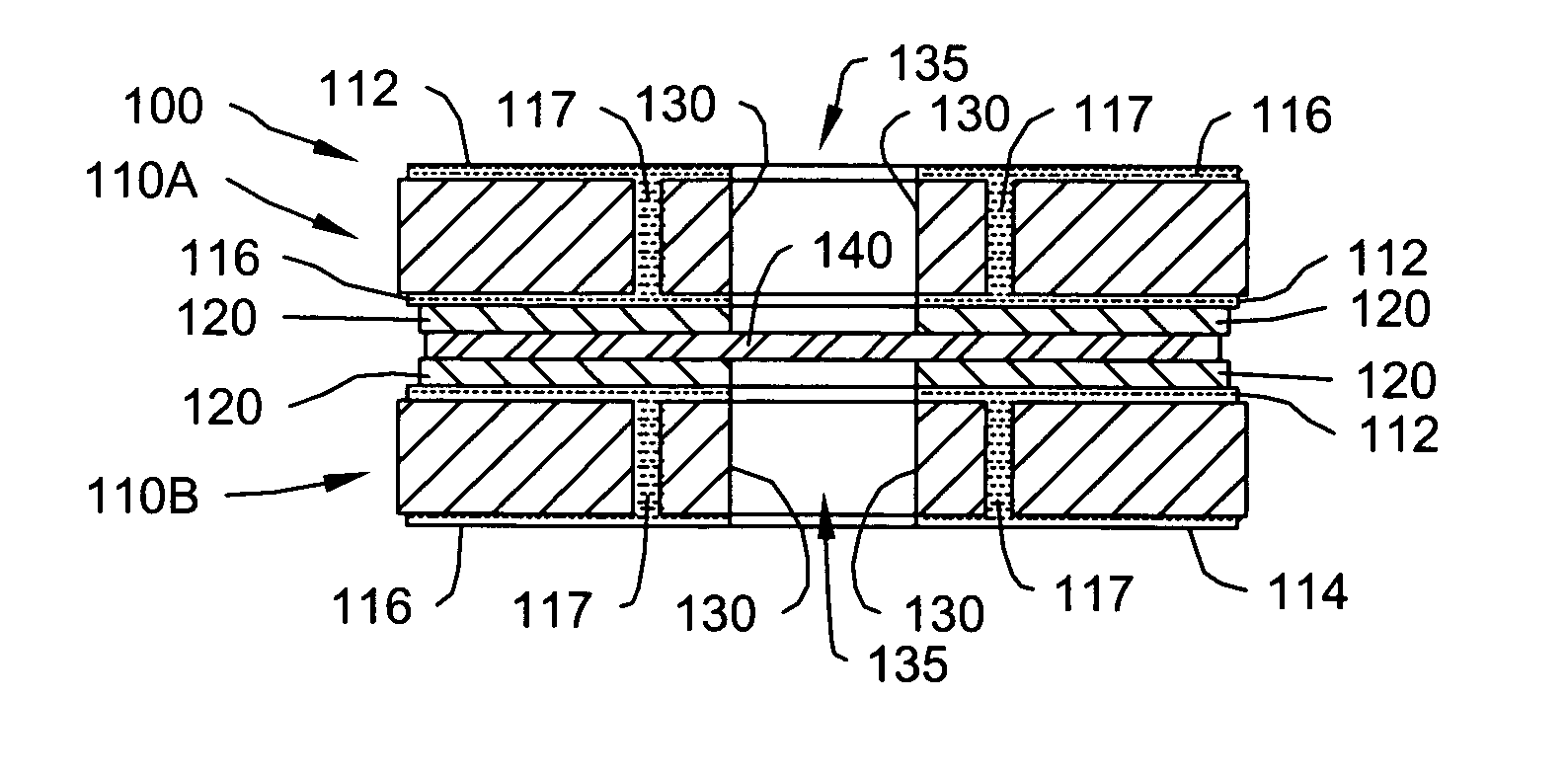
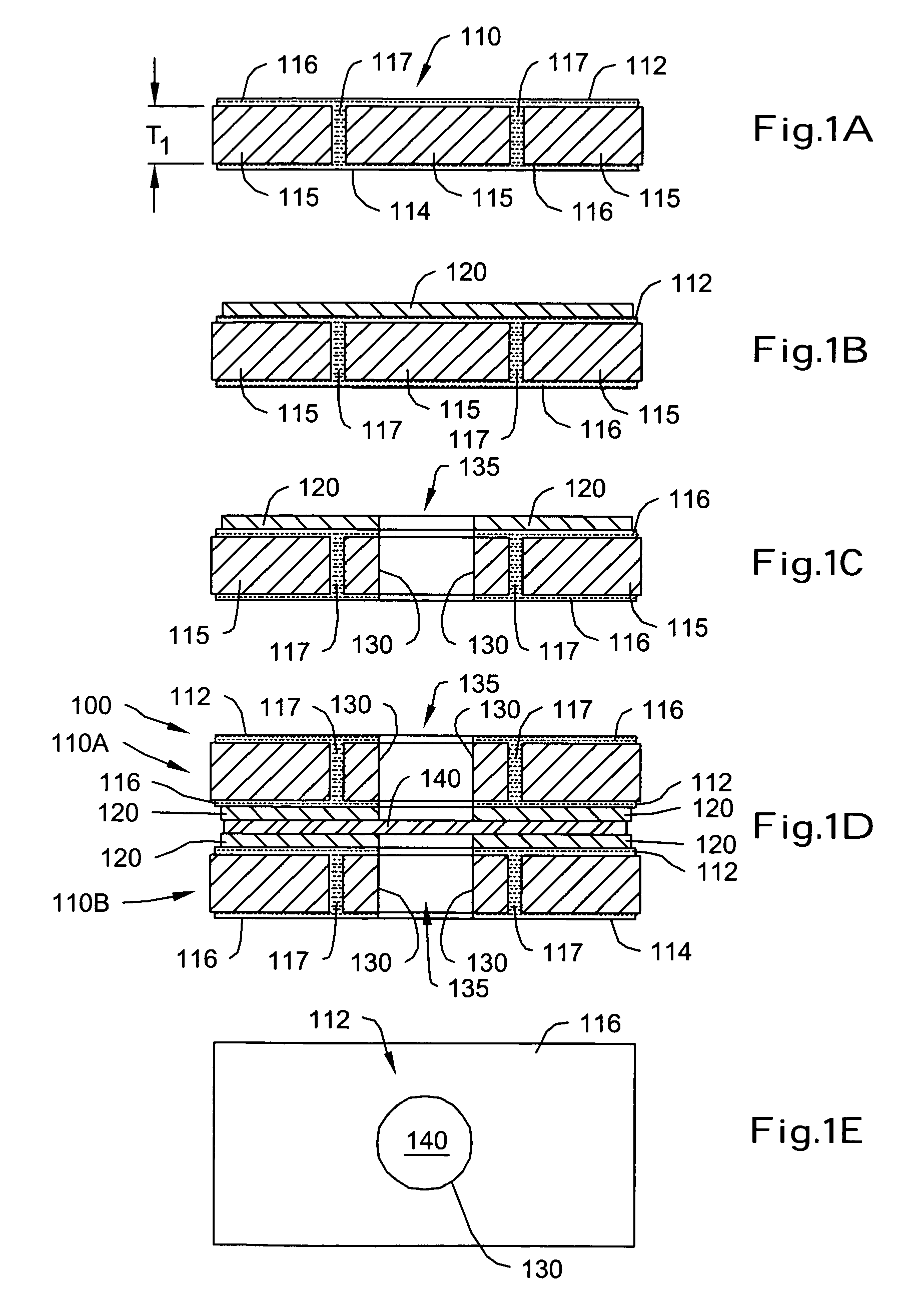
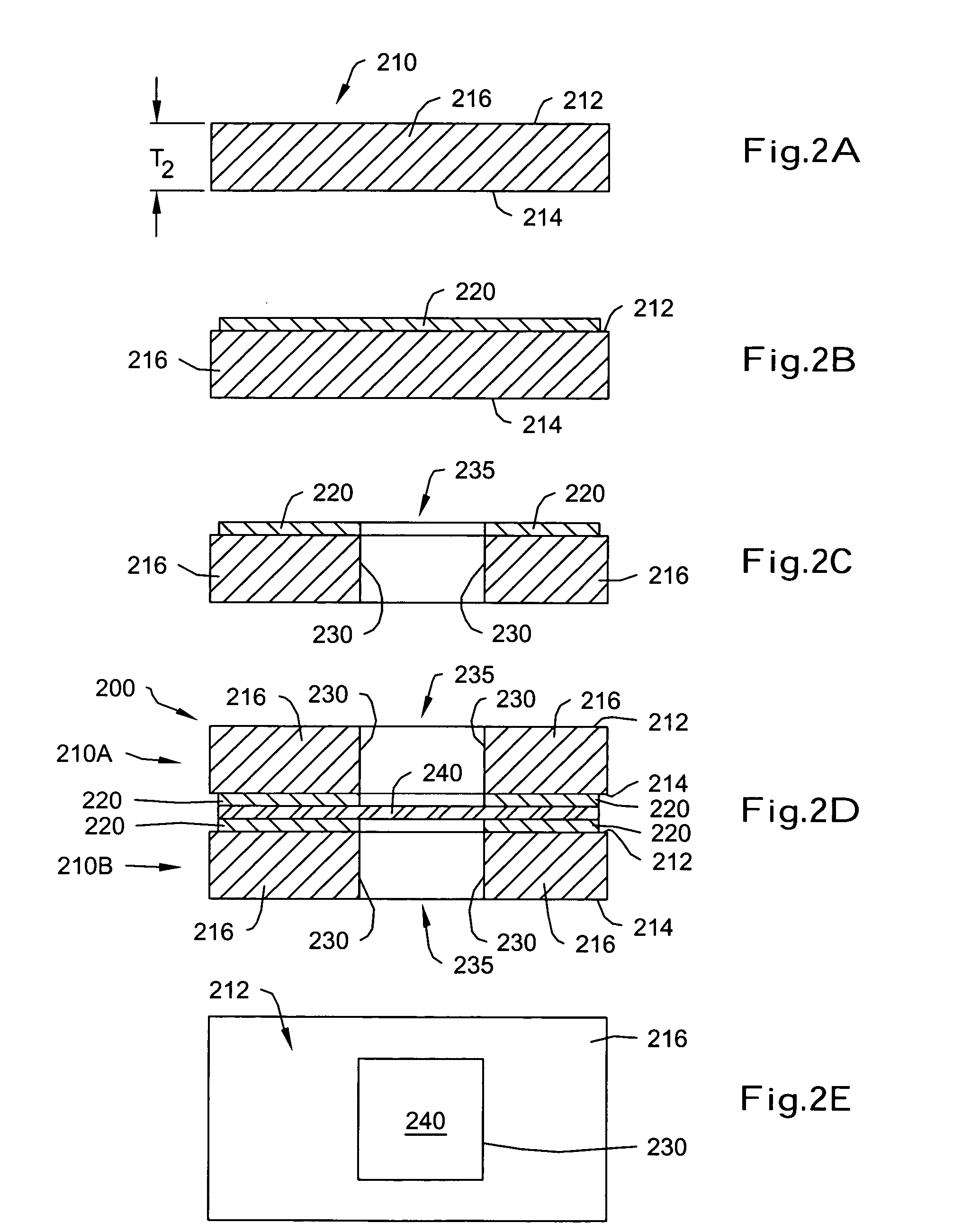
[0007] In some embodiments, and to help promote adhesion between the first electrode layer, the second electrode layer and the proton exchange membrane, an adhesive may be provided between the electrode layers and the proton exchange membrane. Depending on the method of making the fuel cells, the apertures can be formed before or after the adhesive is provided.
[0008] In some embodiments, the first electrode layer and/or the second electrode layer may include a conductive substrate, while in other embodiments, the first electrode layer and/or the second electrode layer may include a non-conductive substrate with a conductive layer applied to at least a portion thereof. When a conductive layer is applied, the conductive layer may be patterned to form one or more fuel cell electrical contacts. In...

Problems solved by technology

Powering of portable and/or wireless electronic devices is a significant issue in today's marketplace.
While the speed and functionality of many wireless sensors and/or portable telecommunications and computing devices tend to be limited by the power source...

Method used


Image

  • Micro fuel cell
  • Micro fuel cell
  • Micro fuel cell

Examples


Embodiment Construction

[0025] The following description should be read with reference to the drawings, in which like elements in different drawings are numbered in like fashion. The drawings, which are not necessarily to scale, depict selected embodiments and are not intended to limit the scope of the invention. Although examples of construction, dimensions, and materials may be illustrated for the various elements, those skilled in the art will recognize that many of the examples provided have suitable alternatives that may be utilized.

[0026] The present invention is applicable for use with all devices, and in particular, those devices that can use small sized power sources. In some illustrative embodiments, the present invention provides electrical power using hydrogen and oxygen as a fuel source. While the present invention is not so limited, an appreciation of various aspects of the invention will be gained through a discussion of the various illustrative embodiments and examples provided below.

[002...


PUM

PropertyMeasurementUnit
Thicknessaaaaaaaaaa
Thicknessaaaaaaaaaa
Areaaaaaaaaaaa

Abstract

A fuel cell, fuel cell array and methods of forming the same are disclosed. The fuel cell can be made by forming a first aperture defined by a first aperture surface through a first electrode layer and forming a second aperture defined by a second aperture surface through a second electrode layer. A proton exchange membrane is laminated between the first electrode layer and the second electrode layer. At least a portion of the first aperture is at least partially aligned with the second aperture.

Description

[0001] This application claims priority to U.S. patent application Ser. No. 10 / 750,581, filed Dec. 29, 2003, entitled “Micro Fuel Cell.”FIELD OF THE INVENTION [0002] The present invention generally relates to the field of fuel cells, and more particularly, to micro fuel cells and methods of making the same. BACKGROUND OF THE INVENTION [0003] A fuel cell produces electrical energy by electrochemically oxidizing a fuel such as hydrogen or methanol in the cell to directly convert the chemical energy of the fuel into electrical energy. Fuel cells have recently drawn attention as a clean supply source for electrical energy. [0004] Powering of portable and / or wireless electronic devices is a significant issue in today's marketplace. While the speed and functionality of many wireless sensors and / or portable telecommunications and computing devices tend to be limited by the power sources, the availability of good power sources is lagging behind development of the electronic devices themselv...

Claims


Application Information

Patent Timeline
IPC IPC(8): H01M8/00H01M8/02H01M8/04H01M8/10H01M8/24
CPCH01M8/0247H01M8/04089H01M8/1004H01M8/1011H01M8/1023Y10T156/1056H01M8/241H01M2250/30Y02E60/521Y02B90/18Y10T156/1062H01M8/1039Y02B90/10Y02E60/50
Inventor WOOD, ROLAND A.REZACHEK, TOM
Owner HONEYWELL INT INC
Why Eureka
Try Eureka