
Shaft structure with adjustable and self-regulated stiffness

a shaft structure and self-regulation technology, applied in the direction of golf clubs, racket sports, thin material handling, etc., can solve the problems of significant change in internal shaft pressure and thus in shaft stiffness

Inactive Publication Date: 2005-11-24
QUALIZZA GREGORY
View PDF8 Cites 17 Cited by
  • Summary
  • Abstract
  • Description
  • Claims
  • Application Information

AI Technical Summary

Benefits of technology

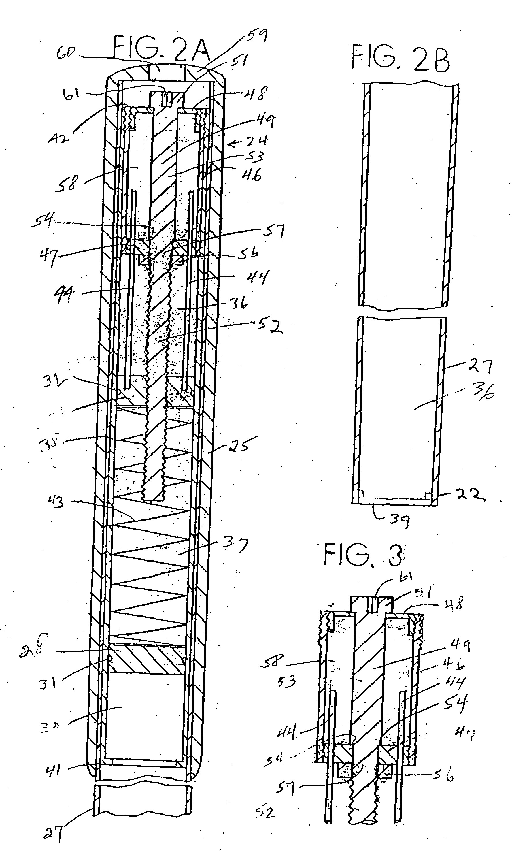
[0011] The piston assumes a longitudinal location in the shaft where the pressure of fluid (preferably a gas, though a liquid may be employed, if desired) in the first chamber and hence the force imposed upon the piston is approximately equal to force imposed upon the piston by the spring. When external environmental temperature changes cause fluid pressure in the first chamber to change, the piston slidably moves in the shaft until the respective force in the first chamber are equalized by the force created by the spring biasing means, thereby to maintain a selected shaft stiffness.
[0021] Another object of the present invention is to provide a fishing rod structure which allows a fisherman to select the stiffness desired for his fishing rod and where once selected the rod will self-maintain the selected thickness regardless of environmental temperature changes.

Problems solved by technology

So far as is known, these fluid charged, variable stiffness, hollow shaft structures of the prior art suffer from the problem that a change in the external environmental temperature inherently causes a significant change in the internal shaft pressure and thus in the shaft stiffness.

Method used


Image

  • Shaft structure with adjustable and self-regulated stiffness
  • Shaft structure with adjustable and self-regulated stiffness
  • Shaft structure with adjustable and self-regulated stiffness

Examples


example

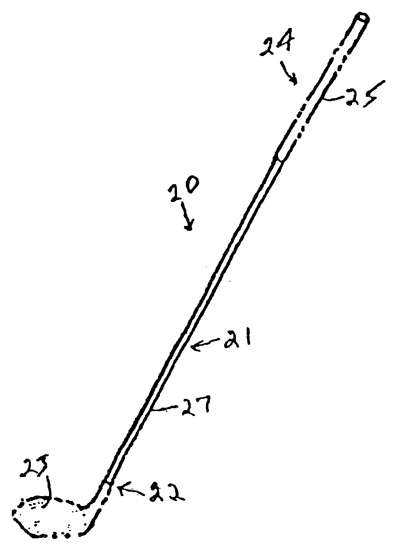
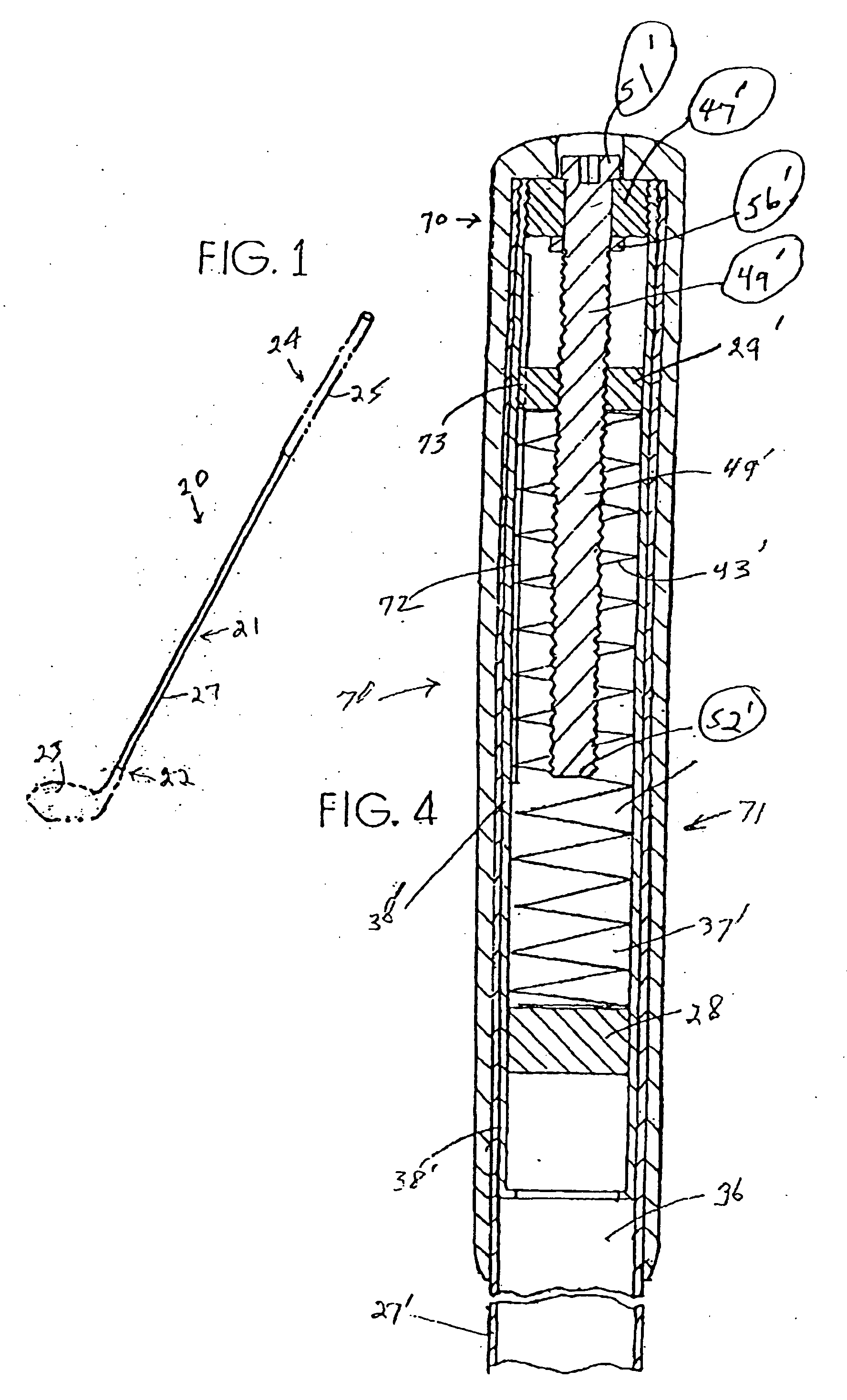
[0085] In golf club 20, as the environmental temperature T increases, the shaft 21 internal pressure P increases in accordance with the so called ideal gas equation (1):

PV=nRT  (1)

where: [0086] P=gas pressure [0087] V=volume of gas [0088] n=number of moles of gas [0089] R=a constant [0090] T=temperature

[0091] In the prior art, the volume of the shaft interior is constant so that pressure must necessarily increase giving rise to an increase in shaft stiffness. In club 20, as T increases, the pressure P increases proportionately according to equation (1). In order for the pressure P in chamber 36 to remain constant, the volume V must necessarily decrease a proportionate amount when in a static mode (that is, a use situation where the golfer is not adjusting the stiffness of the shaft 71 by changing the position of the movable platen 29). As the environmental temperature increases, the pressure in chamber 36 increases and produces a force F upon the piston 28 as summarized by equat...


PUM


Abstract

A shaft structure with adjustable and self-regulating stiffness is provided for golf clubs, fishing rods, and the like. The shaft structure employs in a presently preferred form a hollow tube in which a piston and a longitudinally spaced platen, each longitudinally slidable, are incorporated. The piston and platen are separated from one another by a spring biasing member. The platen is position controlled longitudinally by a longitudinally extending jackscrew that is rotatable and threadably associated with that platen, but that is longitudinally fixed relative to the tube. The chamber defined on one side of the piston contains a fluid which can be a gas or a liquid, and the platen assumes a position along the shaft which to corresponds to a location where forces on each side of the piston are equalized. Rotating the jack screw causes the platen to move longitudinally, the direction depending upon the direction of jackscrew rotation. This movement causes the piston to relocate to a position where the respective pressures on each side thereof remain equalized.

Description

FIELD OF THE INVENTION [0001] This invention relates to shafts for golf clubs, fishing rods and the like wherein shaft stiffness is adjustable and automatically regulated by controlling internal fluid pressures within hollow portions of the shaft. BACKGROUND OF THE INVENTION [0002] Golf shafts are typically manufactured with a predetermined stiffness or flex. The term “stiffness” refers to a shaft's flex characteristics. A golfer can choose among golf shafts of different stiffnesses produced by various manufacturers. However, one manufacturer's “regular” flex could be another manufacturer's “stiff” flex, and vice versa. [0003] It is well known that the stiffness or flex of a golf shaft plays a fundamental role in the behavioral characteristics of a golf club. The stiffness of a golf club shaft and the so-called kick point affect, for example, the launch angle or trajectory of the ball and the distance of ball travel. A shaft can have a high kick point (maximum bend closer to the gri...

Claims


Application Information

Patent Timeline
Patent Type & Authority Applications(United States)
IPC IPC(8): A63B53/10A63B53/12A63B53/14A63B59/00
CPCA63B53/145A63B59/0014A63B2225/62A63B2059/0081A63B59/0074A63B60/06A63B60/08A63B60/10A63B60/24A63B60/42A63B60/0081Y10T137/0396A63B53/14
Inventor QUALIZZA, GREGORY
Owner QUALIZZA GREGORY
Learn More